Horizontal Scale-out of Versa SD-WAN Appliance at DC/Hub Site
Written By Yusuf Fidvi
Introduction:
A Versa SD-WAN appliance at a Datacenter or a Hub site could run out of capacity because the network traffic volume has increased beyond the appliance limits or new services like advanced security were enabled in the VOSTM configuration which caused a reduction in the traffic handling capacity of the appliance. When this happens it becomes necessary to either replace the appliance with a higher end model or add a new appliance to horizontally scale out and distribute the traffic load. Replacing the appliance to a higher end model might not be possible in the short-term but there is a feasible alternative which is to horizontally scale-out by adding more SD-WAN appliances to distribute the traffic load. Adding more appliances rather than replacing them ensures a higher return on investment (ROI) on the older appliances. When adding more SD-WAN appliances, it is recommended to keep the traffic flows symmetric which means that the forward and reverse direction of each flow should pass through the same SD-WAN appliance in the DC irrespective of whether the traffic flow as initiated by a client at a remote site or a server at the Datacenter. When applying security services, it is even required that the traffic flows remain symmetric for proper security inspection.Solution description:
This document describes a solution to help architect such a horizontal scale-out of the Versa appliances at the DC or a Hub in an SD-WAN network. In this solution, we group multiple remote sites in a logical group which are then assigned to a pair of SD-WAN appliances in the Datacenter for redundancy. Some enterprise have a single Datacenter design in which these pair of SD-WAN appliances reside in the same Datacenter. In the case that the enterprise has a disaster recovery Datacenter then these pair of appliances can reside on each of the Datacenter’s for geographic redundancy. For ease of planning, it is generally preferred that all the SD-WAN appliances in the Datacenter are of the same hardware model but this is not a requirement. The traffic load on each SD-WAN Datacenter appliance should be planned in such a way that it is not running out of throughput capacity and there is enough room for the traffic to burst. Depending on the various services applied, the traffic capacity of each appliance model will vary. Refer the Versa appliance datasheet for more information about its maximum throughput capacity.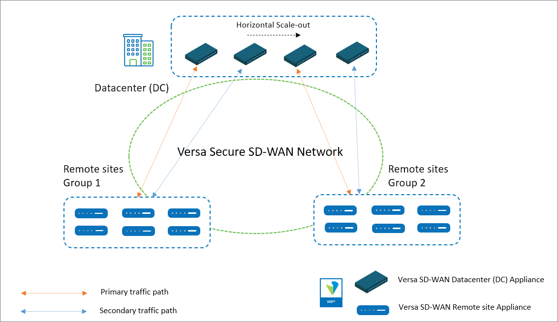
Figure: Versa Secure SD-WAN Network with horizontal scaling of the SD-WAN appliances at the DC
The figure above shows four Versa SD-WAN appliances in the DC with two logical groups of remote sites. 1:1 redundancy means that each SD-WAN appliance in the DC is backed up by another appliance of equal or more capacity. We can also have an N:1 redundancy which means that one SD-WAN appliance at the Datacenter can serve as a backup for multiple other appliances. The implication of an N:1 design is that there can only be a failure of a single appliance at one time without any impact to traffic. Based on the throughput capacity of the SD-WAN appliances at the Datacenter, an estimation of the traffic volume from each remote site should be made. Versa Analytics can be used to make this estimation. The remote sites that need to communicate with the DC can be grouped and assigned to a pair of SD-WAN appliances at the DC, one appliance as the primary and the other as a secondary for redundancy. There is no limit to the number of SD-WAN appliances that can be added in the DC to manage the traffic load. There can be as many groups of SD-WAN appliances and each group should have a minimum of one appliance in it.In general, there are two ways to design this solution.
-
- Routing policies with BGP path metric manipulation
- SD-WAN policies
To understand the design and configuration, let’s look at a full-mesh network where the Datacenter has 3 Versa SD-WAN appliances with 2:1 redundancy. Each Versa appliance in the Datacenter is configured as a separate site without selecting the High Availability options selected in Director Workflow configuration or Concerto Master Profile configuration. There are two remote site appliances, each in its own group.
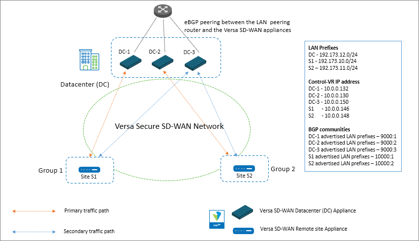
Figure: Versa Secure SD-WAN Network with 3 DC Versa SD-WAN appliances
For Site S1 in Group 1, the Datacenter SD-WAN appliance DC-1 is the primary and appliance DC-3 is the secondary. For Site S2 in Group 2, the Datacenter SD-WAN appliance DC-2 is the primary and appliance DC-3 is the secondary.Note that the High Availability (HA) configuration is not selected under Director Workflows or Concerto Master Profiles when building the DC appliance configuration. Usually on the DC sites, the same WAN links are connected directly to all the SD-WAN appliances thereby not requiring the use of the cross-connect interface. The implication of not selecting HA is that there will be an SD-WAN SLA formed between the DC appliances even if they are physically located on the same site. There is almost negligible load added due to these additional SLA’s but the benefit is that it’s easy to change routing policies for horizontally scaling out with new appliances.
1. Horizontal scale-out using routing policies with BGP path metric manipulation
In this section, we will describe the solution that uses BGP path metric manipulation to influence the traffic flow in both directions.1.1 Traffic Flow – From Remote Site to DC
To ensure that the remote site appliance sends the traffic to the correct DC appliance, the BGP path metrics of the received DC LAN prefixes are modified on each remote site appliance so the routing table on these appliances have the next hop pointing to the correct DC appliance.Below cli output from the remote S1 site appliance shows the DC LAN prefix 192.173.12.0/24 received over MP-BGP.
admin@S1-cli> show route table l3vpn.ipv4.unicast receive-protocol bgp 192.173.12.0/24

Routes for Routing instance : SP-Control-VR  AFI: ipv4  SAFI: unicast

Routing entry for 192.173.12.0/24
   Peer Address       : 10.0.0.6
   Route Distinguisher: 199L:133
   Next-hop           : 10.0.0.130
   VPN Label          : 24704
   Local Preference   : 110
   AS Path            : 64500
   Origin             : Egp
   MED                : 0
   Community          : 8000:1 8000:1 8001:124 8001:139 8002:126 8002:140 8003:129 8004:130 8009:8009 8010:0 8011:0 8011:0 8011:4
   Extended community : target:199L:199
   Preference         : Default
   Weight             : 0

Routing entry for 192.173.12.0/24
   Peer Address       : 10.0.0.6
   Route Distinguisher: 199L:134
   Next-hop           : 10.0.0.132
   VPN Label          : 24704
   Local Preference   : 110
   AS Path            : 64500
   Origin             : Egp
   MED                : 0
   Community          : 8000:1 8000:1 8001:124 8001:139 8002:126 8002:140 8003:129 8004:130 8009:8009 8010:0 8011:0 8011:0 8011:4
   Extended community : target:199L:199
   Preference         : Default
   Weight             : 0

Routing entry for 192.173.12.0/24
   Peer Address       : 10.0.0.6
   Route Distinguisher: 199L:143
   Next-hop           : 10.0.0.150
   VPN Label          : 24704
   Local Preference   : 110
   AS Path            : 64500
   Origin             : Egp
   MED                : 0
   Community          : 8000:1 8000:1 8001:124 8001:139 8002:126 8002:140 8003:129 8004:130 8009:8009 8010:0 8011:0 8011:0 8011:4
   Extended community : target:199L:199
   Preference         : Default
   Weight             : 0
As seen above, all the DC SD-WAN appliances are advertising the prefix with the same local preference 110. The route table on the LAN VR of the remote site router as shown below has all the routes installed with ECMP load-balancing.
admin@S1-cli> show route routing-instance SP-Enterprise 192.173.12.0/24

Routes for Routing instance : SP-Enterprise  AFI: ipv4  SAFI: unicast
[+] - Active Route

Routing entry for 192.173.12.0 (mask 255.255.255.0) [+]
Known via 'BGP', distance 200,
   Redistributing via BGP
   Last update from 10.0.0.130 7s ago
Routing Descriptor Blocks:
* 10.0.0.130 , via Indirect 7s ago

Routing entry for 192.173.12.0 (mask 255.255.255.0) [+]
Known via 'BGP', distance 200,
   Redistributing via BGP
   Last update from 10.0.0.132 5s ago
Routing Descriptor Blocks:
* 10.0.0.132 , via Indirect 5s ago

Routing entry for 192.173.12.0 (mask 255.255.255.0) [+]
Known via 'BGP', distance 200,
   Redistributing via BGP
   Last update from 10.0.0.150 7s ago
Routing Descriptor Blocks:
* 10.0.0.150 , via Indirect 7s ago
To make the remote site S1, choose the DC-1 appliance as primary and DC-3 appliance as secondary, the Local Preference of the route received from these appliances need to be increased. BGP communities are used to tag and identify the DC LAN routes advertised from each of the DC appliances over MP-BGP. These communities are set when receiving these prefixes over the eBGP connection to the LAN peering router.
On the DC-1 appliance, the routes received on the LAN interface from the peering router over eBGP are tagged with a BGP community of 9000:1.
Following are the steps required to add the BGP community to the prefixes received from the LAN peering router over BGP.
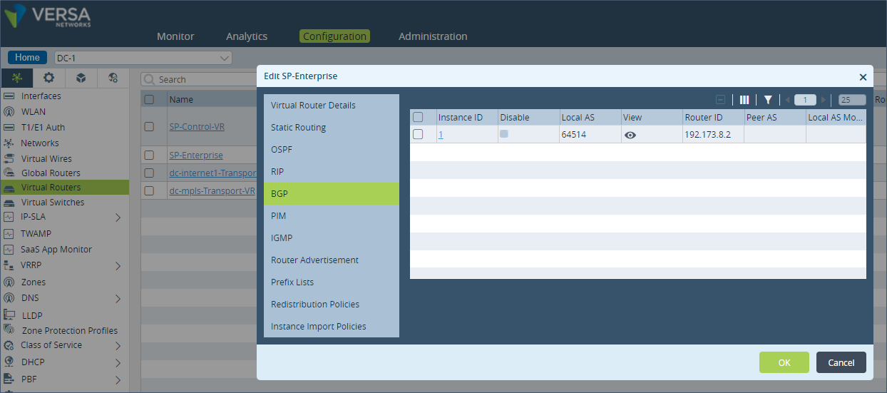
Step 1: Under “Networking” and “Virtual Routers”, click on the LAN virtual routing instance. In this example it is “SP-Enterprise”. Navigate to the BGP configuration tab in the Virtual Router configuration section.
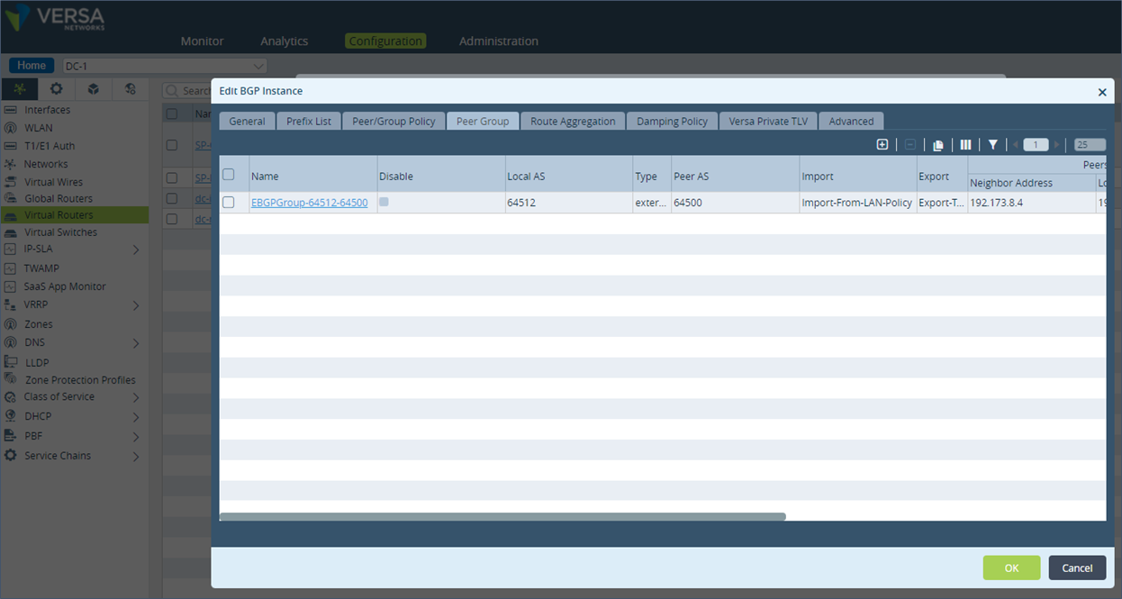
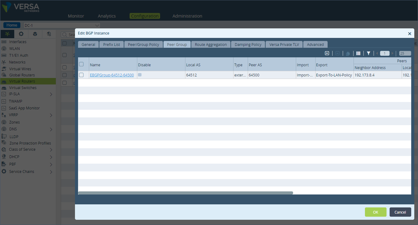
 Step 2: Click on the BGP Instance ID and go to “Peer Group” configuration. Verify the name of the Import policy applied. In the example, the policy “Import-From-LAN-Policy” is already applied in the import policy configuration for the LAN eBGP neighbor.
 Step 3: Go to the “Peer/Group” configuration and click on the “Import-From-LAN-Policy”.
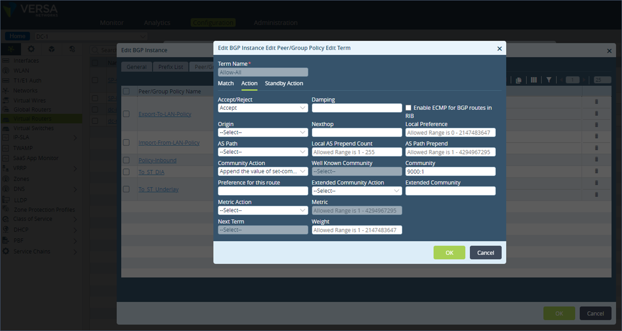
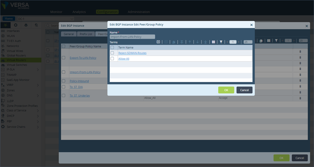 Step 4: Edit the term “Allow-All” and under Action, set the Community Action to “Append the value of set-community into the communities list” and then add the Community value of 9000:1 and save the configuration.
 Configuration described above in cli format
set routing-instances SP-Enterprise protocols bgp 1 routing-peer-policy Import-From-LAN-Policy term Allow-All action accept
set routing-instances SP-Enterprise protocols bgp 1 routing-peer-policy Import-From-LAN-Policy term Allow-All action community 9000:1
set routing-instances SP-Enterprise protocols bgp 1 routing-peer-policy Import-From-LAN-Policy term Allow-All action community-action set-specific
set routing-instances SP-Enterprise protocols bgp 1 routing-peer-policy Import-From-LAN-Policy term Allow-All action rib-bgp-ecmp false
The above configuration steps apply the BGP community value to the BGP learnt prefixes from the LAN peering router. To set the community value for a directly connected route or static route on the DC-1 appliance, follow the below steps.
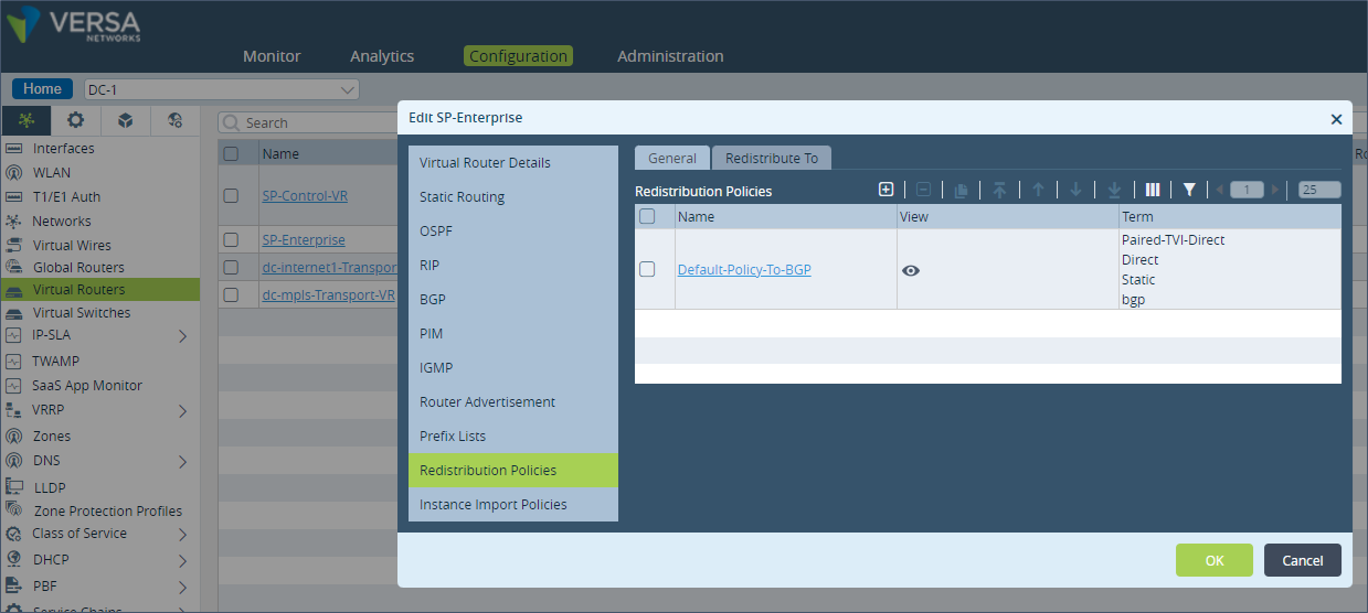
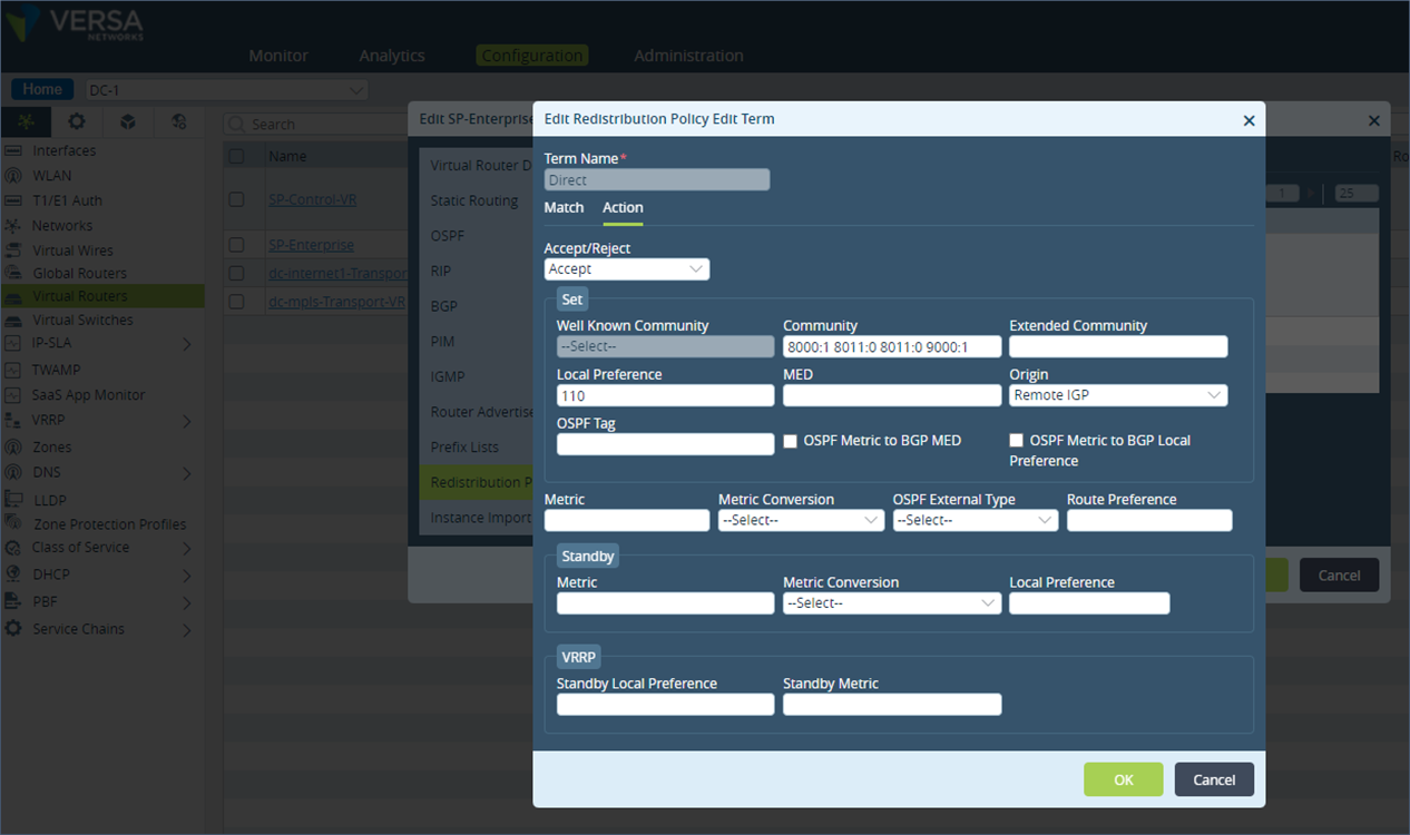
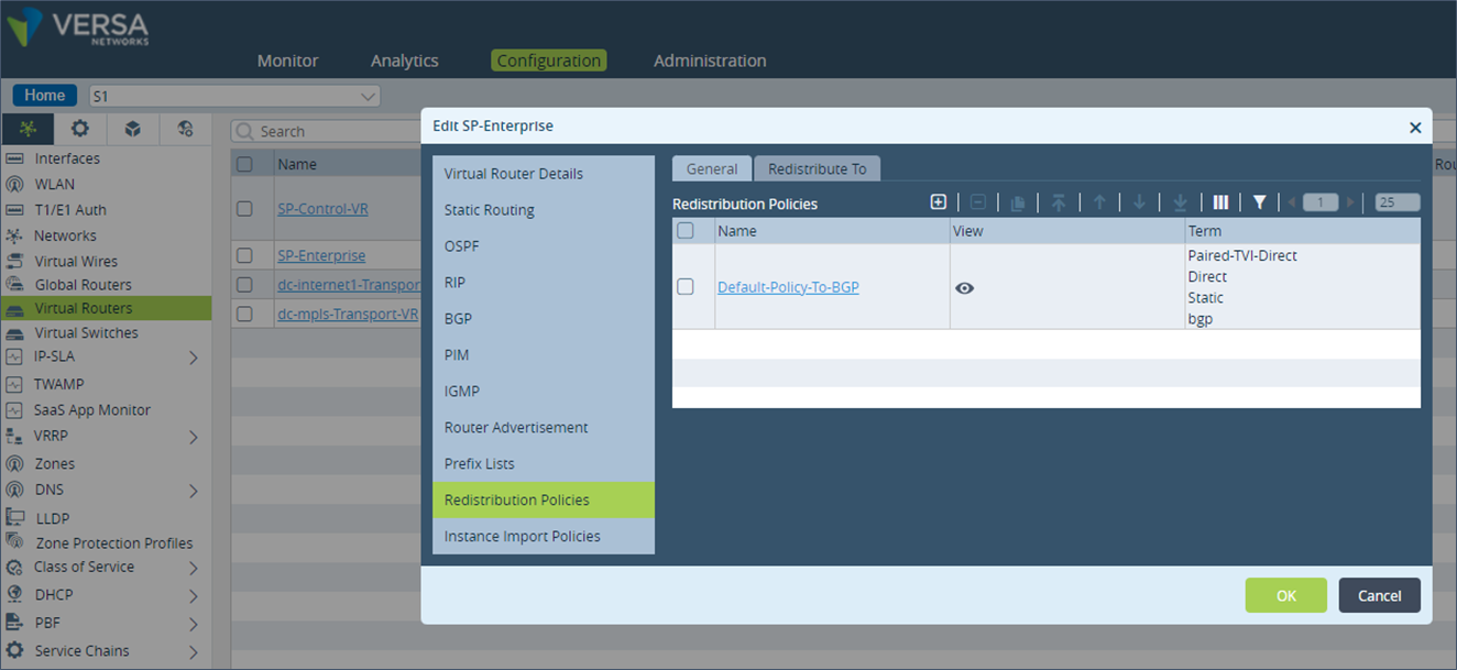
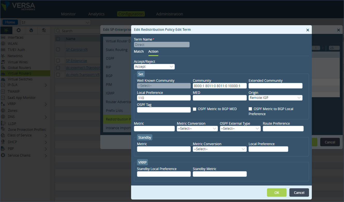
Step 1: Under “Networking”, go to “Virtual Routers” and select the LAN VR “SP-Enterprise”. Click on “Redistribution Policies” and select the “Default-Policy-To-BGP”.
 Step 2: Click on the term “Direct”.
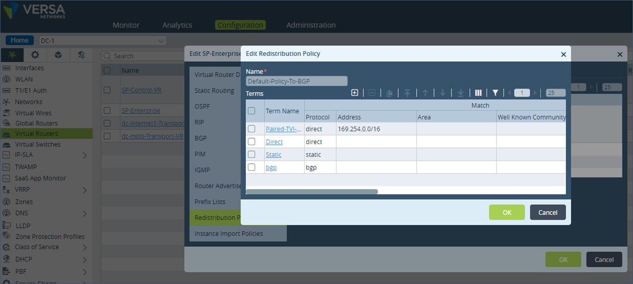 Step 3: Under “Action”, add the community 9000:1 at the end of the already existing BGP community list and save the configuration.
 Similarly, repeat the same configuration steps as described above for the term “Static” in the “Default-Policy-to-BGP” policy configuration.
Configuration described above in cli format
Similarly, repeat the same configuration steps as described above for the term “Static” in the “Default-Policy-to-BGP” policy configuration.
Configuration described above in cli format
set routing-instances SP-Enterprise policy-options redistribution-policy Default-Policy-To-BGP term Direct match protocol direct
set routing-instances SP-Enterprise policy-options redistribution-policy Default-Policy-To-BGP term Direct action accept
set routing-instances SP-Enterprise policy-options redistribution-policy Default-Policy-To-BGP term Direct action set-community "8001:139 8002:140 8001:124 8002:126 8010:0 8000:1 8011:0 8011:0 9000:1"
set routing-instances SP-Enterprise policy-options redistribution-policy Default-Policy-To-BGP term Direct action set-origin igp
set routing-instances SP-Enterprise policy-options redistribution-policy Default-Policy-To-BGP term Direct action set-local-preference 110
set routing-instances SP-Enterprise policy-options redistribution-policy Default-Policy-To-BGP term Static match protocol static
set routing-instances SP-Enterprise policy-options redistribution-policy Default-Policy-To-BGP term Static action accept
set routing-instances SP-Enterprise policy-options redistribution-policy Default-Policy-To-BGP term Static action set-community "8001:139 8002:140 8001:124 8002:126 8010:0 8000:1 8011:0 8011:0 9000:1"
set routing-instances SP-Enterprise policy-options redistribution-policy Default-Policy-To-BGP term Static action set-origin igp
set routing-instances SP-Enterprise policy-options redistribution-policy Default-Policy-To-BGP term Static action set-local-preference 110
Note that there is a term called “BGP” under the “Default-Policy-to-BGP” policy. This term can be used to add the BGP community to the LAN received prefixes instead of changing the import policy configuration on the LAN eBGP peer. But doing this will also result in the BGP community getting added to the prefixes advertised by this appliance to this LAN peer.
Similar to the DC-1 appliance configuration shown above, the DC-2 and DC-3 appliances have the BGP community 9000:2 and 9000:3 tagged to their LAN prefixes.
On the remote site SD-WAN appliance S1, we see the communities 9000:1, 9000:2 & 9000:3 added to the BGP learnt prefixes from the DC appliances DC-1, DC-2 & DC-3.
admin@S1-cli> show route table l3vpn.ipv4.unicast receive-protocol bgp 192.173.8.0/24

Routes for Routing instance : SP-Control-VR  AFI: ipv4  SAFI: unicast

Routing entry for 192.173.8.0/24
   Peer Address       : 10.0.0.6
   Route Distinguisher: 199L:133
   Next-hop           : 10.0.0.130
   VPN Label          : 24704
   Local Preference   : 110
   AS Path            : N/A
   Origin             : Igp
   MED                : 0
   Community          : 8000:1 8001:124 8001:139 8002:126 8002:140 8009:8009 8010:0 8011:0 8011:0 9000:2
   Extended community : target:199L:199
   Preference         : Default
   Weight             : 0

Routing entry for 192.173.8.0/24
   Peer Address       : 10.0.0.6
   Route Distinguisher: 199L:134
   Next-hop           : 10.0.0.132
   VPN Label          : 24704
   Local Preference   : 110
   AS Path            : N/A
   Origin             : Igp
   MED                : 0
   Community          : 8000:1 8001:124 8001:139 8002:126 8002:140 8009:8009 8010:0 8011:0 8011:0 9000:1
   Extended community : target:199L:199
   Preference         : Default
   Weight             : 0

Routing entry for 192.173.8.0/24
   Peer Address       : 10.0.0.6
   Route Distinguisher: 199L:143
   Next-hop           : 10.0.0.150
   VPN Label          : 24704
   Local Preference   : 110
   AS Path            : N/A
   Origin             : Igp
   MED                : 0
   Community          : 8000:1 8001:124 8001:139 8002:126 8002:140 8009:8009 8010:0 8011:0 8011:0 9000:3
   Extended community : target:199L:199
   Preference         : Default
   Weight             : 0
Next on the remote site S1, we will modify the BGP local-preference value of the MP-BGP prefix received from site DC-1 with community value 9000:1. Step 1: Go to the “Virtual Routers” configuration and select BGP and click on the “Instance ID”.
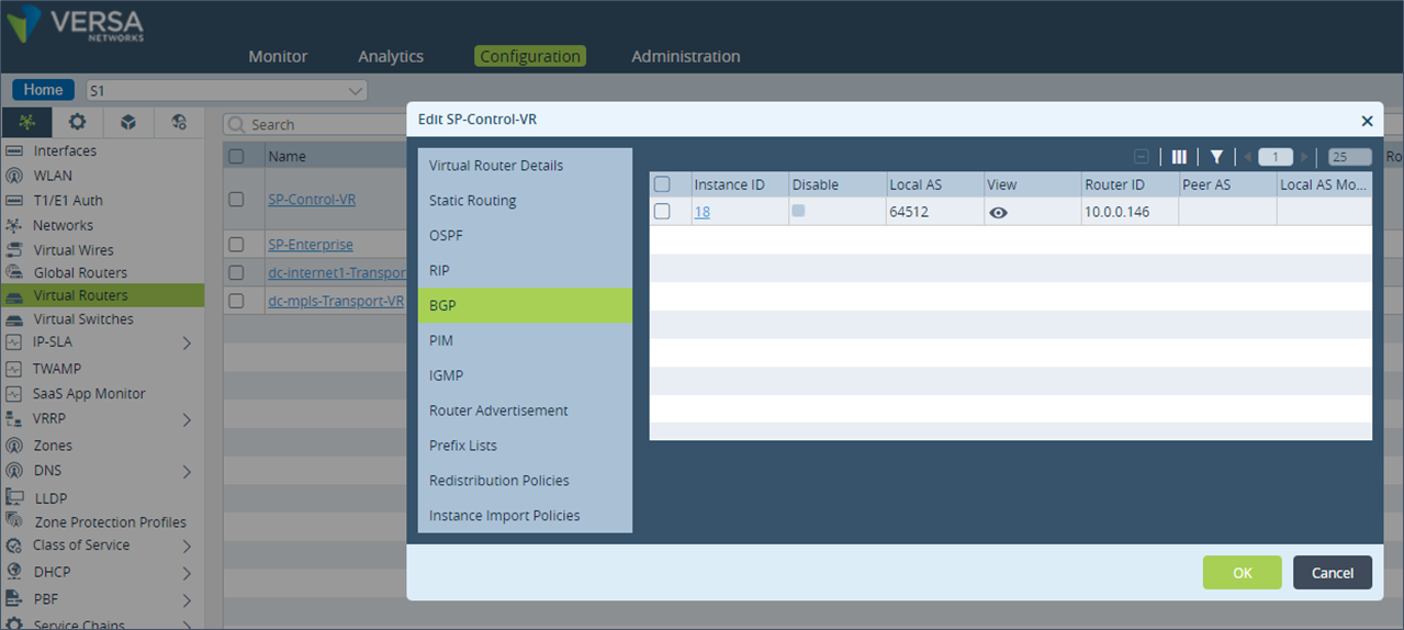 Step 2: Check which BGP Import policy is applied for the MP-BGP session towards the Controllers. Note the name of the Import policy applied. In this example, the policy name is “Import-From-Hubs-Policy”.
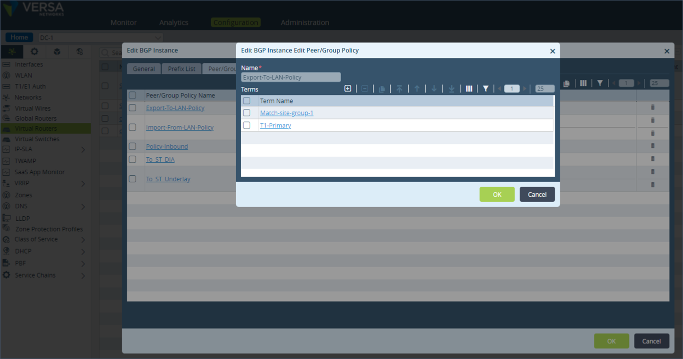
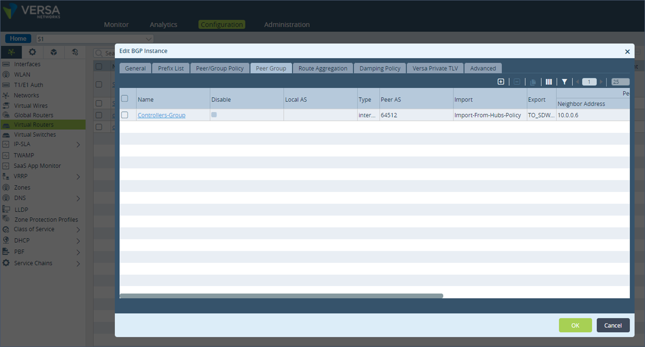 Step 3: Go on the Peer/Group Policy section and click on the policy name “Import-From-Hubs-Policy”.
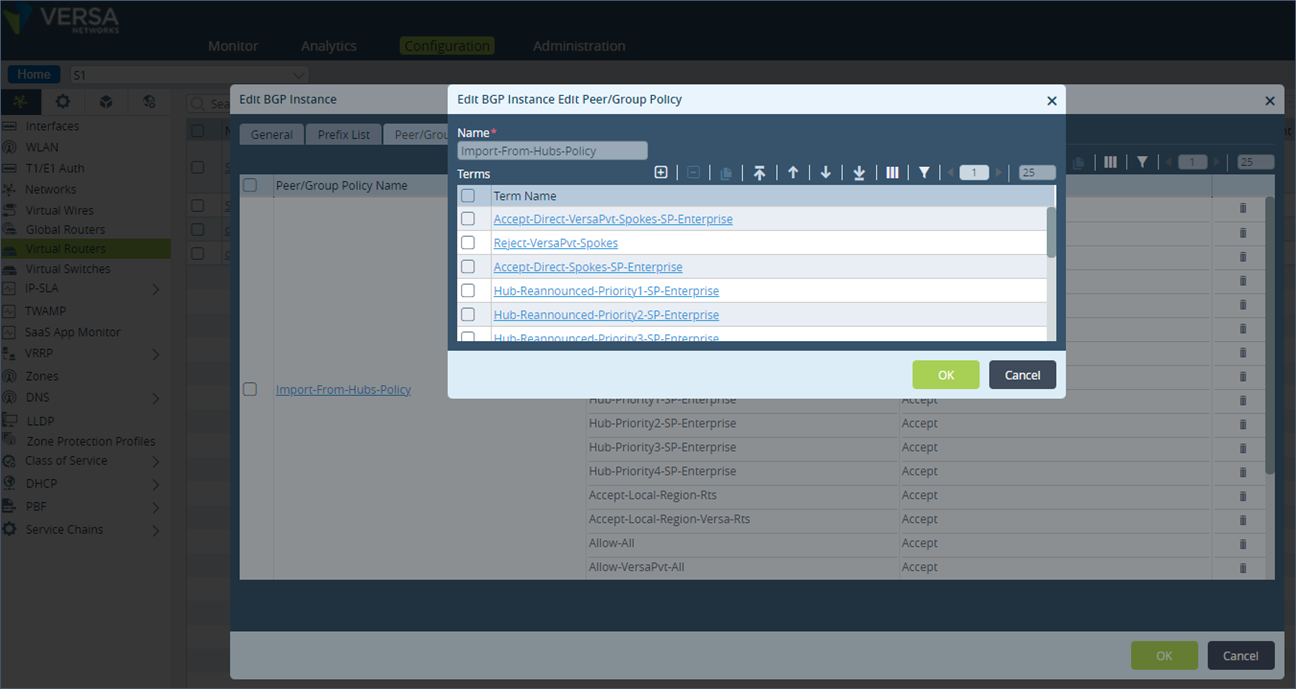 Step 4: Add a new term “DC-AP-1”. Match the community value of 9000:1.
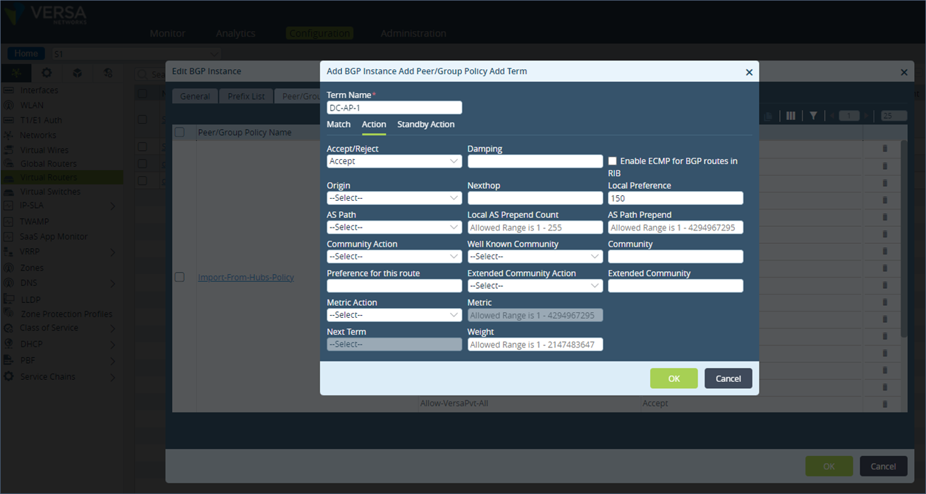
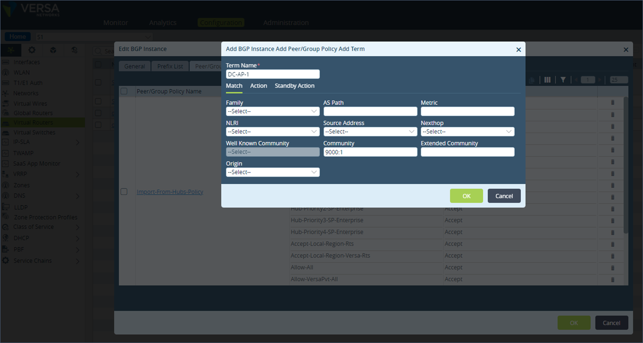 Step 5: Under Action, set the local preference to 150 and save the configuration.
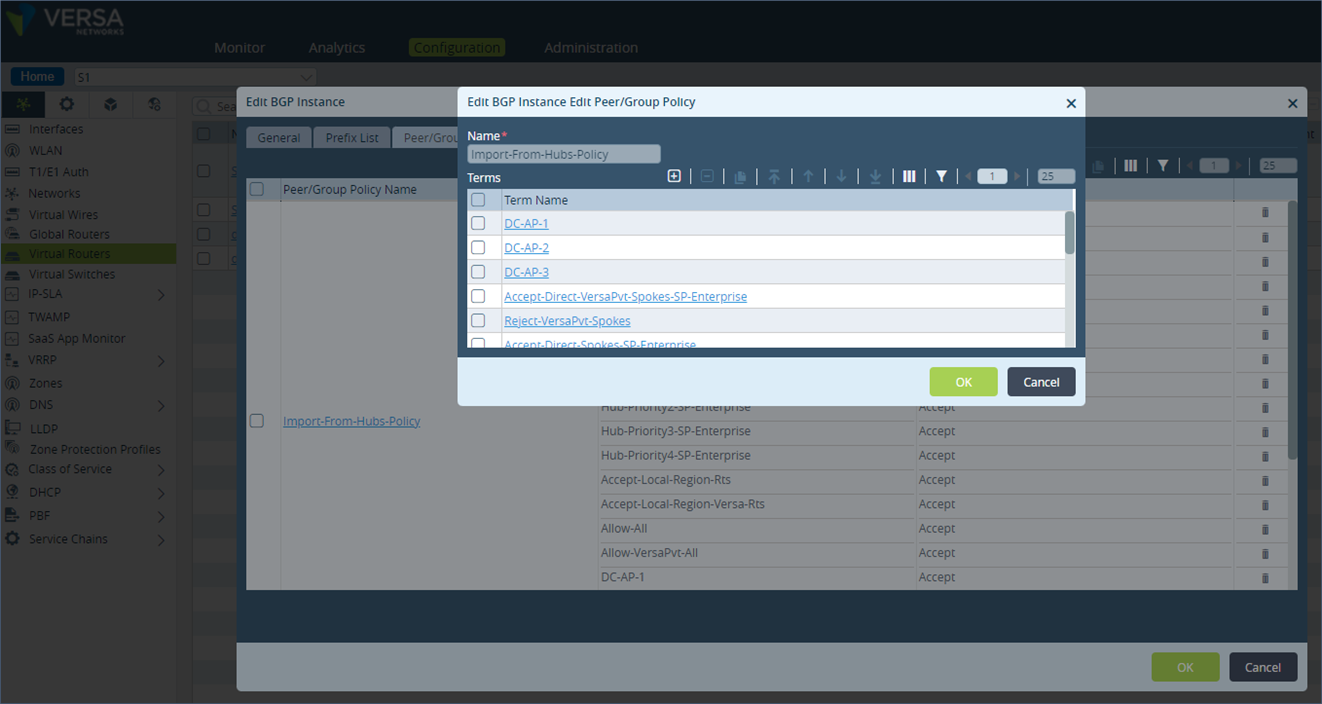
 Step 6: The new term gets appended at the end in the list of all terms under the policy. Move the newly added term to the top of the term list using the UP arrow button.
 Step 7: Similarly, add a term (DC-AP-2 & DC-AP-3) for the community values 9000:2 and 9000:3. Set their local preference to 148 and 149 respectively. Ensure these terms are also on top of the list.
 Configuration described above in cli format
set routing-instances SP-Control-VR protocols bgp 18 routing-peer-policy Import-From-Hubs-Policy term DC-AP-1 match community 9000:1
set routing-instances SP-Control-VR protocols bgp 18 routing-peer-policy Import-From-Hubs-Policy term DC-AP-1 action accept
set routing-instances SP-Control-VR protocols bgp 18 routing-peer-policy Import-From-Hubs-Policy term DC-AP-1 action set-local-preference 150
set routing-instances SP-Control-VR protocols bgp 18 routing-peer-policy Import-From-Hubs-Policy term DC-AP-1 action rib-bgp-ecmp false
set routing-instances SP-Control-VR protocols bgp 18 routing-peer-policy Import-From-Hubs-Policy term DC-AP-3 match community 9000:3
set routing-instances SP-Control-VR protocols bgp 18 routing-peer-policy Import-From-Hubs-Policy term DC-AP-3 action accept
set routing-instances SP-Control-VR protocols bgp 18 routing-peer-policy Import-From-Hubs-Policy term DC-AP-3 action set-local-preference 149
set routing-instances SP-Control-VR protocols bgp 18 routing-peer-policy Import-From-Hubs-Policy term DC-AP-3 action rib-bgp-ecmp false
set routing-instances SP-Control-VR protocols bgp 18 routing-peer-policy Import-From-Hubs-Policy term DC-AP-2 match community 9000:2
set routing-instances SP-Control-VR protocols bgp 18 routing-peer-policy Import-From-Hubs-Policy term DC-AP-2 action accept
set routing-instances SP-Control-VR protocols bgp 18 routing-peer-policy Import-From-Hubs-Policy term DC-AP-2 action set-local-preference 148
set routing-instances SP-Control-VR protocols bgp 18 routing-peer-policy Import-From-Hubs-Policy term DC-AP-2 action rib-bgp-ecmp false
If the DC prefix on site S1 should only be learnt from DC-1 and DC-3 appliances and not from the DC-2 appliance, then set the action to reject in the policy term that matches community value 9000:2.
Repeat the steps for the remote site S2 appliance.
After the above mentioned steps are completed, verify that the BGP local preference value is set correctly on the remote site appliance S1 for the DC LAN prefix.
admin@S1-cli> show route table l3vpn.ipv4.unicast receive-protocol bgp 192.173.8.0/24

Routes for Routing instance : SP-Control-VR  AFI: ipv4  SAFI: unicast

Routing entry for 192.173.8.0/24
   Peer Address       : 10.0.0.6
   Route Distinguisher: 199L:133
   Next-hop           : 10.0.0.130
   VPN Label          : 24704
   Local Preference   : 148
   AS Path            : N/A
   Origin             : Igp
   MED                : 0
   Community          : 8000:1 8001:124 8001:139 8002:126 8002:140 8010:0 8011:0 8011:0 9000:2
   Extended community : target:199L:199
   Preference         : Default
   Weight             : 0

Routing entry for 192.173.8.0/24
   Peer Address       : 10.0.0.6
   Route Distinguisher: 199L:134
   Next-hop           : 10.0.0.132
   VPN Label          : 24704
   Local Preference   : 150
   AS Path            : N/A
   Origin             : Igp
   MED                : 0
   Community          : 8000:1 8001:124 8001:139 8002:126 8002:140 8010:0 8011:0 8011:0 9000:1
   Extended community : target:199L:199
   Preference         : Default
   Weight             : 0

Routing entry for 192.173.8.0/24
   Peer Address       : 10.0.0.6
   Route Distinguisher: 199L:143
   Next-hop           : 10.0.0.150
   VPN Label          : 24704
   Local Preference   : 149
   AS Path            : N/A
   Origin             : Igp
   MED                : 0
   Community          : 8000:1 8001:124 8001:139 8002:126 8002:140 8010:0 8011:0 8011:0 9000:3
   Extended community : target:199L:199
   Preference         : Default
   Weight             : 0
Since the DC LAN prefix learnt via DC-1 has the highest Local preference, it is preferred. The route table on S1 only has a single active route in its route table for the DC prefixes. If the primary appliance DC-1 is unreachable then the prefix from the appliance DC-3 gets installed in the route table.
admin@S1-cli> show route routing-instance SP-Enterprise 192.173.8.0/24

Routes for Routing instance : SP-Enterprise  AFI: ipv4  SAFI: unicast
[+] - Active Route

Routing entry for 192.173.8.0 (mask 255.255.255.0)
Known via 'BGP', distance 200,
   Redistributing via BGP
   Last update from 10.0.0.130 3m47s ago
Routing Descriptor Blocks:
* 10.0.0.130 , via Indirect 3m47s ago

Routing entry for 192.173.8.0 (mask 255.255.255.0) [+]
Known via 'BGP', distance 200,
   Redistributing via BGP
   Last update from 10.0.0.132 3m47s ago
Routing Descriptor Blocks:
* 10.0.0.132 , via Indirect 3m47s ago

Routing entry for 192.173.8.0 (mask 255.255.255.0)
Known via 'BGP', distance 200,
   Redistributing via BGP
   Last update from 10.0.0.150 3m47s ago
Routing Descriptor Blocks:
* 10.0.0.150 , via Indirect 3m47s ago
With the configuration described above, the traffic originating from the remote site to the DC will prefer DC–1 appliance and failover to the secondary appliance when the primary appliance fails.
1.1 Traffic Flow – From DC to Remote Site
Now let’s look at the scenario where the traffic originates from the DC towards the remote-sites. Typically in the DC LAN, there is an L3 switch or a site router or a firewall that is connected to the SD-WAN appliance. A routing protocols like BGP or OSPF is typically used to exchange the DC LAN prefixes and remote site LAN prefixes. The routing policy needs to be configured in a way that makes the peering device choose the correct DC SD-WAN appliance to send traffic towards the remote site.BGP path metrics or OSPF cost can be used to determine which SD-WAN appliance will receive traffic destined for a remote site. In the below example we will assume BGP as the routing protocol on the DC LAN between the DC SD-WAN appliance and the peering router. The configuration for OSPF is also similar but not in scope of this document.
First group all the sites in an SD-WAN network that should use a particular DC SD-WAN appliance as primary and secondary for traffic. Then assign a single BGP community for each of these group of sites. In our example, we have two group’s 1 and 2, which have a single site S1 and S2 in it. We will use the community value 10000:1 to tag LAN prefixes from site S1 and 10000:2 for the LAN prefixes from site S2.
In the remote site SD-WAN appliance S1, make the following configuration.
Step 1: Under “Networking”, go to the “Virtual Routers” section and select the SP-Enterprise VR. Click on “Redistribution Policies” and select the “Default-Policy-To-BGP” policy.
 Step 2: In the terms “Direct”, add the BGP community under the “Action” section, append the community 10000:1 to the list of default communities preset. If any routing protocol is used in the remote site then there will be a policy term statement for that routing protocol e.g. BGP or OSPF. Append the community values to these protocol terms as well.
 Step 3: Repeat the above steps to tag BGP community 10000:1 in the term “Static.
Configuration described above in cli format
Step 3: Repeat the above steps to tag BGP community 10000:1 in the term “Static.
Configuration described above in cli format
set routing-instances SP-Enterprise policy-options redistribution-policy Default-Policy-To-BGP term Direct match protocol direct
set routing-instances SP-Enterprise policy-options redistribution-policy Default-Policy-To-BGP term Direct action accept
set routing-instances SP-Enterprise policy-options redistribution-policy Default-Policy-To-BGP term Direct action set-community "8001:139 8002:140 8001:124 8002:126 8010:0 8000:1 8011:0 8011:0 10000:1"
set routing-instances SP-Enterprise policy-options redistribution-policy Default-Policy-To-BGP term Direct action set-origin igp
set routing-instances SP-Enterprise policy-options redistribution-policy Default-Policy-To-BGP term Direct action set-local-preference 110
set routing-instances SP-Enterprise policy-options redistribution-policy Default-Policy-To-BGP term Static match protocol static
set routing-instances SP-Enterprise policy-options redistribution-policy Default-Policy-To-BGP term Static action accept
set routing-instances SP-Enterprise policy-options redistribution-policy Default-Policy-To-BGP term Static action set-community "8001:139 8002:140 8001:124 8002:126 8010:0 8000:1 8011:0 8011:0 10000:1"
set routing-instances SP-Enterprise policy-options redistribution-policy Default-Policy-To-BGP term Static action set-origin igp
set routing-instances SP-Enterprise policy-options redistribution-policy Default-Policy-To-BGP term Static action set-local-preference 110
The LAN prefixes advertised by the remote site S-1 over MP-BGP will now have the community 10000:1 added to it.
admin@S1-cli> show route table l3vpn.ipv4.unicast advertising-protocol bgp 192.173.10.0/24

Routes for Routing instance : SP-Control-VR  AFI: ipv4  SAFI: unicast

Routing entry for 192.173.10.0/24
   Peer Address       : 10.0.0.6
   Route Distinguisher: 199L:141
   Next-hop           : 10.0.0.146
   VPN Label          : 24704
   Local Preference   : 110
   AS Path            : N/A
   Origin             : Igp
   MED                : 0
   Community          : 8000:1 8001:124 8001:139 8002:126 8002:140 8010:0 8011:0 8011:0 10000:1
   Extended community : target:199L:199


On the DC SD-WAN appliance, the same prefix is received with the community 10000:1 added to it.

admin@DC-1-cli> show route table l3vpn.ipv4.unicast receive-protocol bgp 192.173.10.0/24

Routes for Routing instance : SP-Control-VR  AFI: ipv4  SAFI: unicast

Routing entry for 192.173.10.0/24
   Peer Address       : 10.0.0.6
   Route Distinguisher: 199L:141
   Next-hop           : 10.0.0.146
   VPN Label          : 24704
   Local Preference   : 110
   AS Path            : N/A
   Origin             : Igp
   MED                : 0
   Community          : 8000:1 8001:124 8001:139 8002:126 8002:140 8009:8009 8010:0 8011:0 8011:0 10000:1
   Extended community : target:199L:199
   Preference         : Default
   Weight             : 0
In the LAN eBGP configuration of the DC site appliance DC-1 which is the primary appliance for remote site S1, we match the remote site prefixes with a BGP community value of 10000:1 and leave the AS-path prepend value to default i.e. we do not make any change to the AS-path prepend value. For all other prefixes, we set a local-AS-prepend of 5 for all prefixes. On appliance DC-3 which is the secondary DC appliance for remote site S1, the local-AS-prepend value for all prefixes will be 5 and the ones that match the community value of 10000:1 will be set to 2. This ensures that the SD-WAN appliance DC-1 advertises the remote site S1 LAN prefixes to the LAN peering router with the shortest AS path making it the most preferred one. DC-3 which is the secondary DC appliance will advertise a second longest AS path of 2.
In the LAN eBGP configuration of the DC site appliance DC-2 which is the secondary appliance for remote site S2, we match the remote site prefixes with a BGP community value of 10000:2 and leave the AS-path prepend value to default i.e. we do not make any change to the AS-path prepend value. For all other prefixes, we set a local-AS-prepend of 5 for all prefixes. On appliance DC-3 which is the secondary DC appliance for remote site S2, the local-AS-prepend value for all prefixes will be 5 and the ones that match the community value of 10000:2 will be set to 2. This ensures that the SD-WAN appliance DC-AP-2 advertises the remote site S2 LAN prefixes to the LAN peering router with the shortest AS path making it the most preferred one. DC-AP-3 which is the secondary DC appliance will advertise a second longest AS path of 2.
To make the configuration in the LAN eBGP session on the DC-1 appliance follow the below steps. Step 1: Under “Networking”, go to “Virtual Routers” and under the BGP section, click on the “Instance ID” and open the “Peer Group” section. Note the name of the export policy used for the BGP peering on the LAN. If there is no export policy used then a new one should be created.
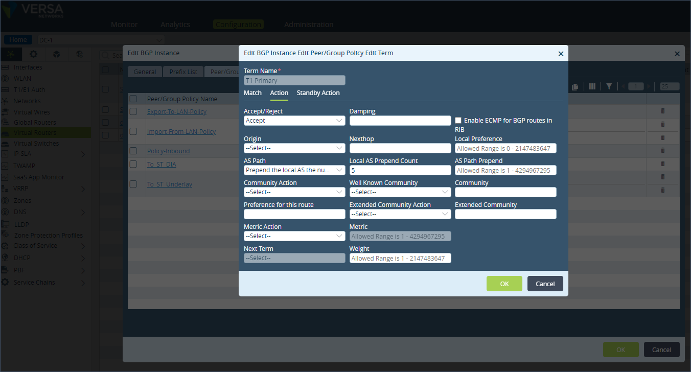
 Step 2: Click on “Peer/Group Policy” and select the term T1-Primary which will matches all prefixes. Here set the “Action” to AS Path “Prepend the local AS the number of times specified by local-as-prepend-count”. Set the “Local AS Prepend Count” value to 5.
 Step 3: Create a new term called “Match-Site-group-1” to match the BGP community value 10000:1. Leave the “Action” field empty which means no AS path prepend is done.
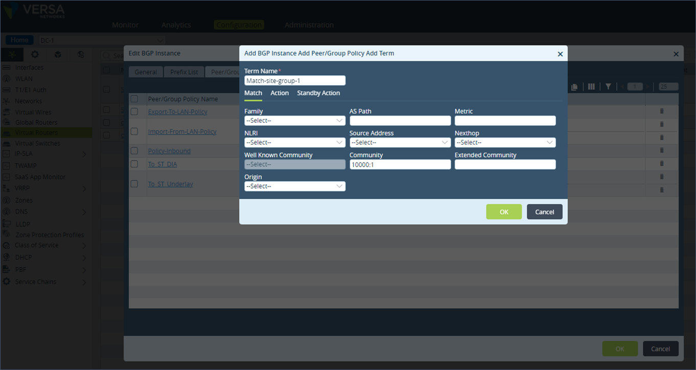 Step 4: In the policy term list, ensure that the policy term statement that matches the BGP community 10000:1 is above the term “T1-Primary” that matches all prefixes.
 Do a similar configuration on DC-3 appliance which is the secondary appliance for the remote site S1. On this appliance, match the BGP community value of 10000:1 and set the AS-path prepend value of 2.
On the LAN peering router, the remote SD-WAN site prefix is learnt with the following AS path attributes for remote site S1 prefix.
Do a similar configuration on DC-3 appliance which is the secondary appliance for the remote site S1. On this appliance, match the BGP community value of 10000:1 and set the AS-path prepend value of 2.
On the LAN peering router, the remote SD-WAN site prefix is learnt with the following AS path attributes for remote site S1 prefix.
admin@ST-3-red-cli> show route table ipv4.unicast receive-protocol bgp 192.173.10.0/24

Routes for Routing instance : SP-Control-VR  AFI: ipv4  SAFI: unicast
% No entries found.

Routes for Routing instance : SP-Enterprise  AFI: ipv4  SAFI: unicast


Prefix/Mask         Next-hop          MED  Lclpref  AS path
-----------         --------          ---  -------  -------
192.173.10.0/24     192.173.8.5       0    100      64512 64512
192.173.10.0/24     192.173.8.3       0    100      64512 64512 64512
192.173.10.0/24     192.173.8.2       0    100      64512
The group prefix received from SD-WAN appliance DC-1 (192.173.8.2) is preferred over the secondary peer DC-3 (192.173.8.5) due to its shorter AS-path value as seen in the routing table output below.
admin@ST-3-red-cli> show route routing-instance SP-Enterprise 192.173.10.0/24

Routes for Routing instance : SP-Enterprise  AFI: ipv4  SAFI: unicast
[+] - Active Route

Routing entry for 192.173.10.0 (mask 255.255.255.0) [+]
Known via 'BGP', distance 20,
   Redistributing via BGP
   Last update from 192.173.8.2 3h8m27s ago
Routing Descriptor Blocks:
* 192.173.8.2 , via Indirect 3h8m27s ago
Similarly, the remote site S2 prefix in group 2 prefers the DC-2 appliance path as seen in the output below.
admin@ST-3-red-cli> show route table ipv4.unicast receive-protocol bgp 192.173.11.0/24

Routes for Routing instance : SP-Control-VR  AFI: ipv4  SAFI: unicast
% No entries found.

Routes for Routing instance : SP-Enterprise  AFI: ipv4  SAFI: unicast


Prefix/Mask         Next-hop          MED  Lclpref  AS path
-----------         --------          ---  -------  -------
192.173.11.0/24     192.173.8.5       0    100      64512 64512
192.173.11.0/24     192.173.8.3       0    100      64512
192.173.11.0/24     192.173.8.2       0    100      64512 64512 64512


admin@ST-3-red-cli> show route routing-instance SP-Enterprise 192.173.11.0/24

Routes for Routing instance : SP-Enterprise  AFI: ipv4  SAFI: unicast
[+] - Active Route

Routing entry for 192.173.11.0 (mask 255.255.255.0) [+]
Known via 'BGP', distance 20,
   Redistributing via BGP
   Last update from 192.173.8.3 3h23m45s ago
Routing Descriptor Blocks:
* 192.173.8.3 , via Indirect 3h23m45s ago
1. Horizontal scale-out using SD-WAN policies
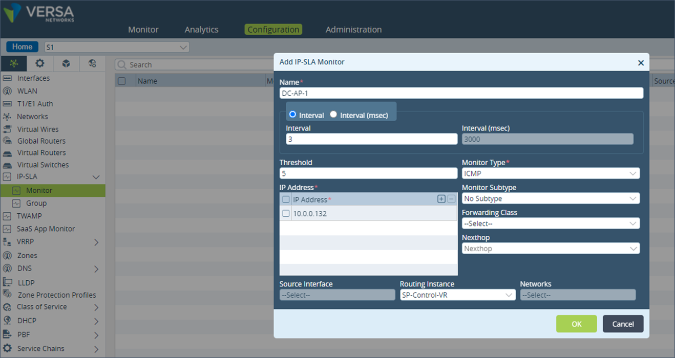
Traffic Flow – From Remote Site to DC Path preference to DC appliances from the remote sites can also be done using an SD-WAN policy. In the SD-WAN policy, we define a forwarding profile with the next hop set to the DC appliances in the order of priority.Step 1: On the remote site S1, click on “IP-SLA” under “Networking” and create a new “Monitor”. In the Monitor, select the “Monitor Type” field as ICMP, “Routing Instance” field as SP-Control-VR and in “IP Address” field, add the tvi interface IP address of the DC-1 appliance. Add a new Monitor for the secondary DC-3 appliance as well.
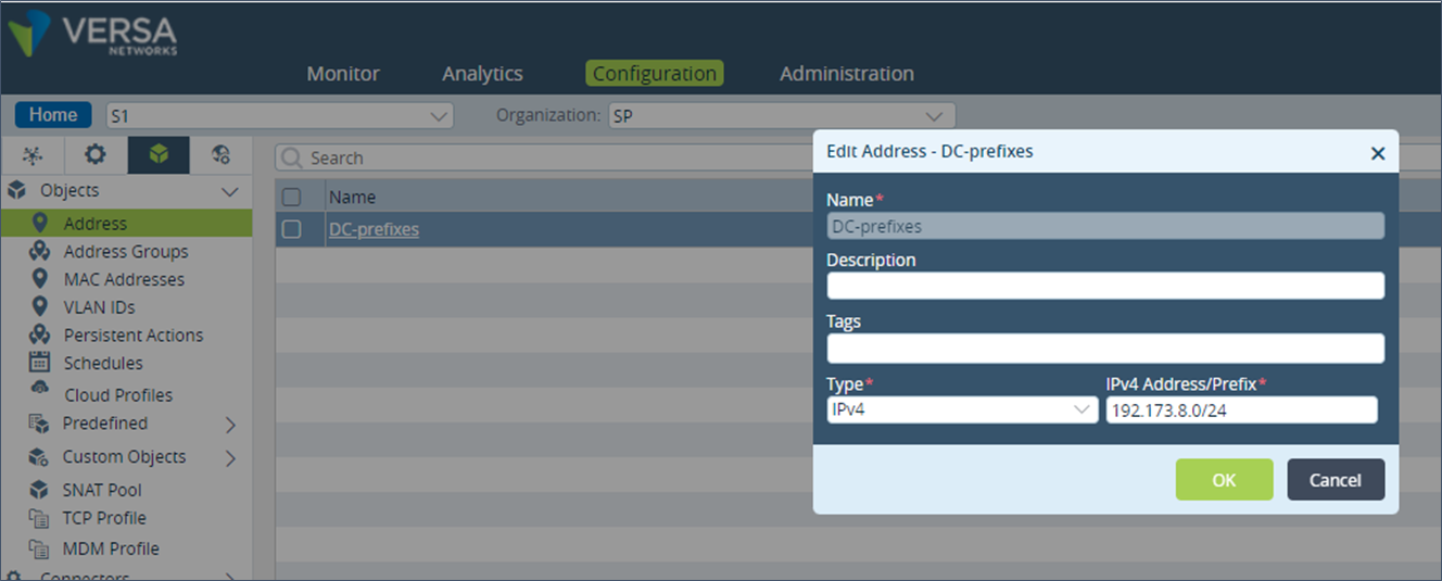
 Step 2: Step 5: Under “Objects & Connectors”, go to “Objects” and then click on “Address”. Create a new Address and add the DC prefixes. If there are more than one DC prefixes, an Address Group can be created instead.
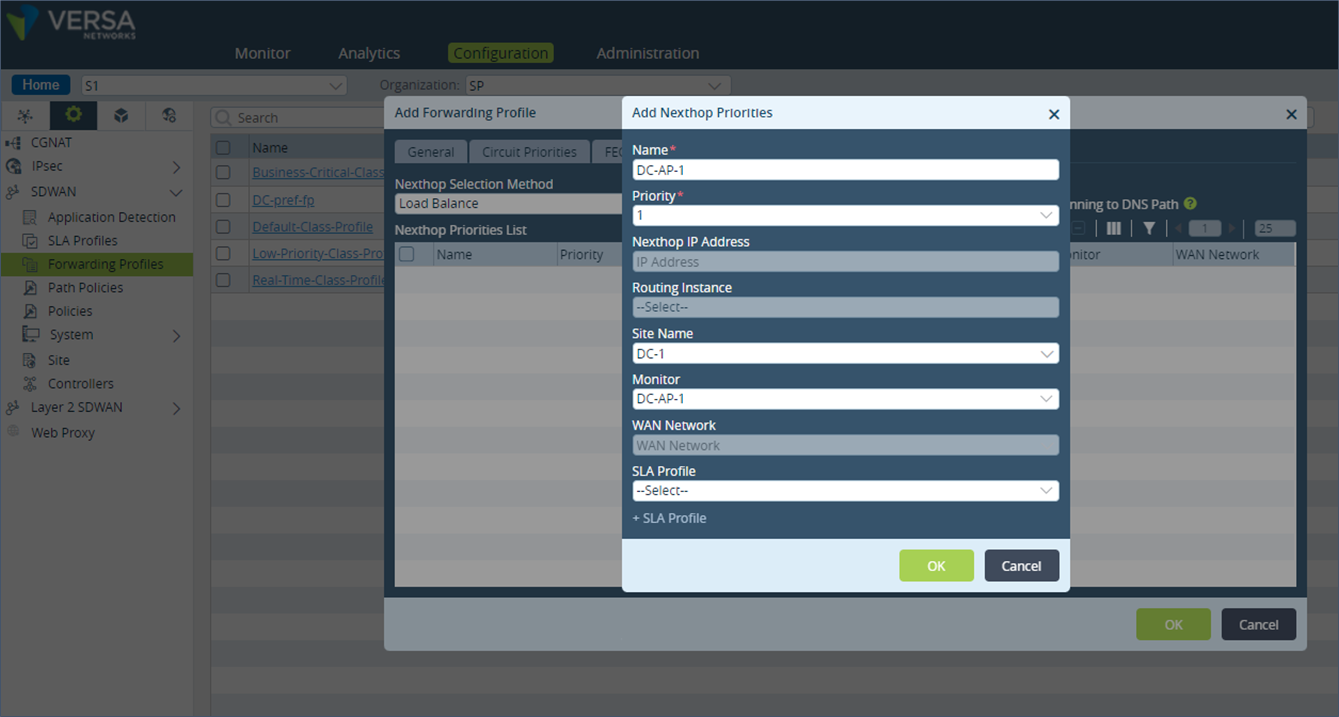
 Step 3: Under “Services”, create a new SD-WAN Forwarding Profile and click on the “Nexthop” option.
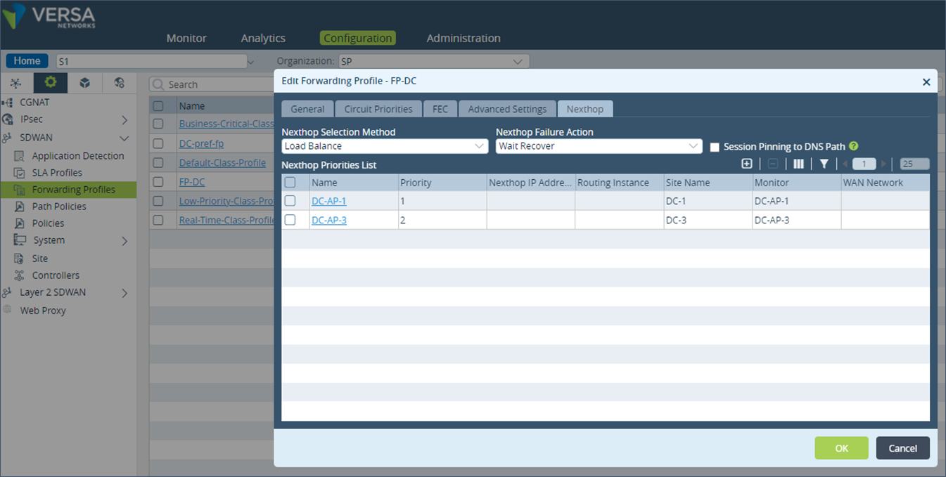
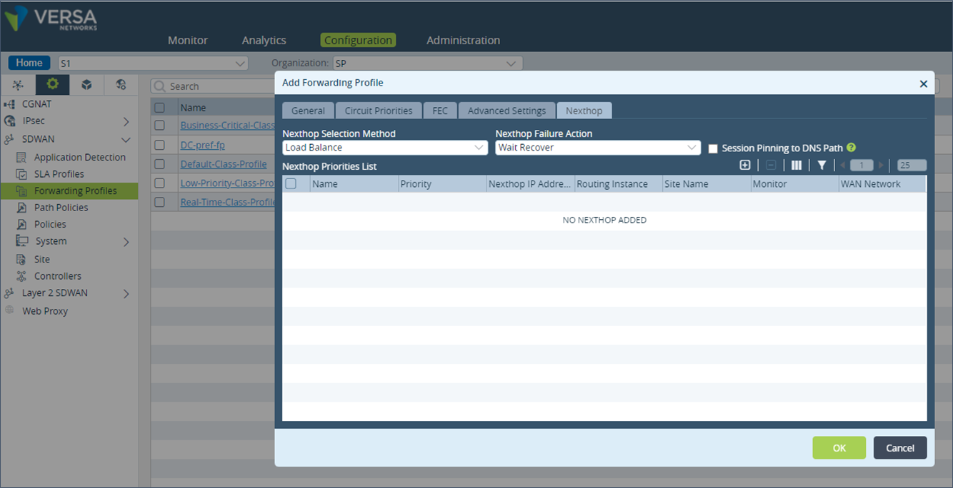 Step 3: Add a new entry in the “Nexthop Priorities List” and select the “Priority” value to 1. In the “Site Name” field, select the DC-1 appliance and select the Monitor created in the last step.
 Step 4: Repeat the above step for the DC-3 appliance which should be added as Priority 2.
 Step 6: Create a new SD-WAN Policy.
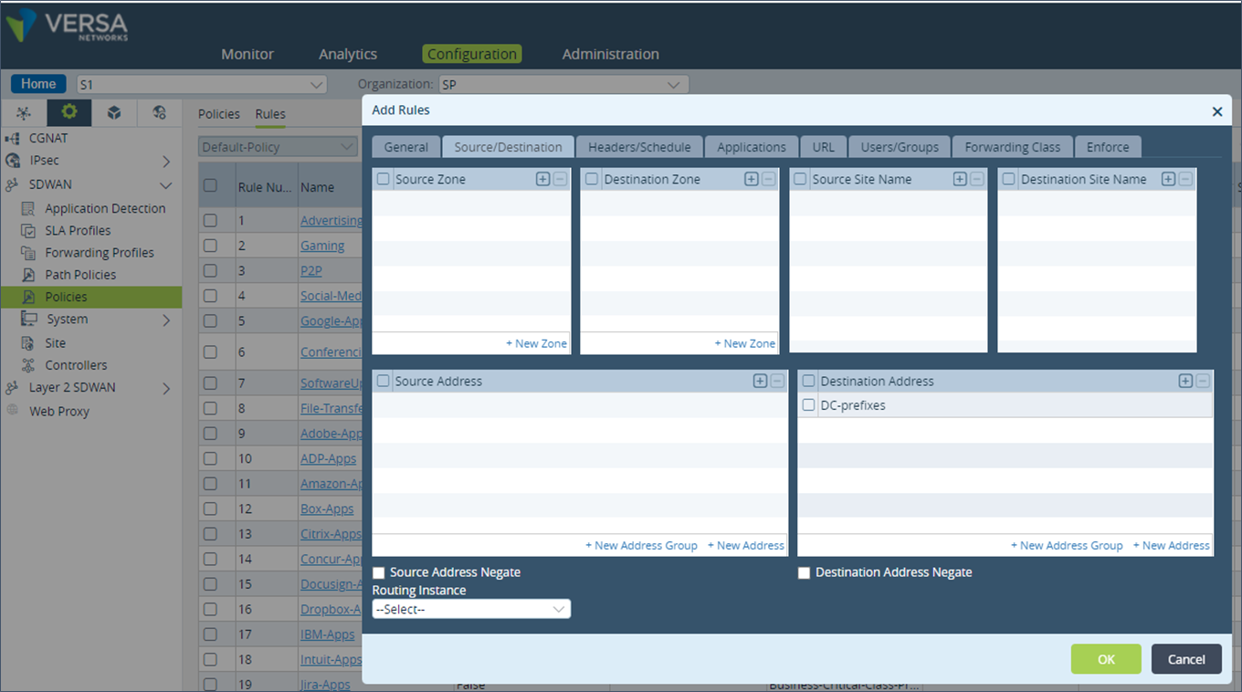
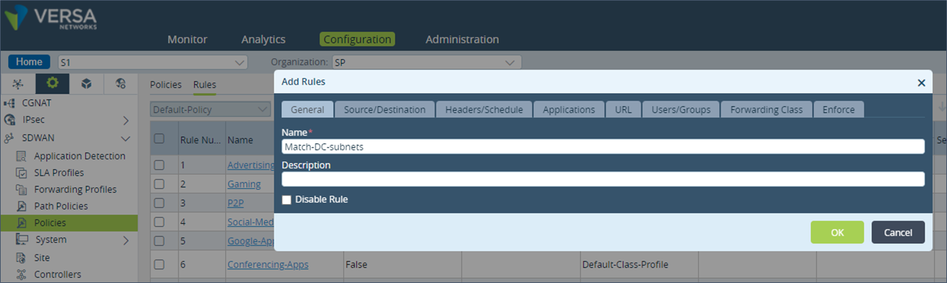 Step 7: Under “Source/Destination”, add the DC prefixes address in the “Destination Address” field.
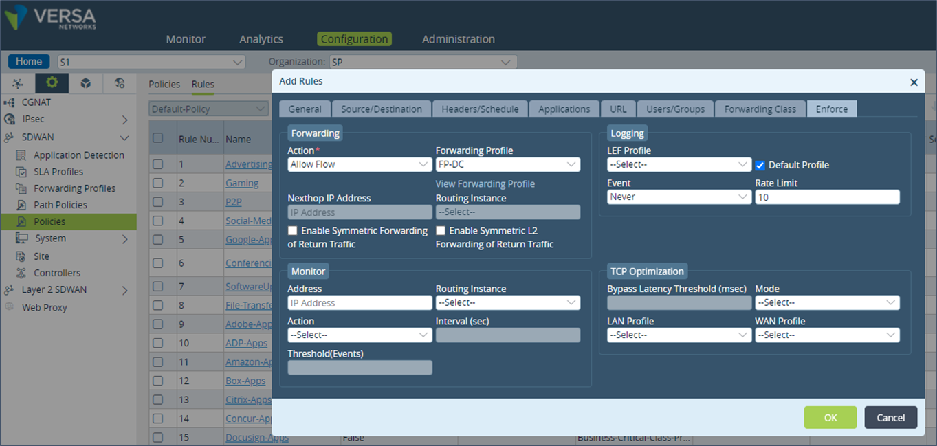
 Step 8: In the “Enforce” tab, add the “Forwarding Profile” created earlier and save the configuration.
 Configuration described above in cli format
set orgs org-services SP objects addresses DC-prefixes ipv4-prefix 192.173.8.0/24

set monitor DC-AP-1 interval 3
set monitor DC-AP-1 threshold 5
set monitor DC-AP-1 type icmp
set monitor DC-AP-1 sub-type none
set monitor DC-AP-1 routing-instance SP-Control-VR
set monitor DC-AP-1 ip-addresses [ 10.0.0.132 ]
set monitor DC-AP-3 interval 3
set monitor DC-AP-3 threshold 5
set monitor DC-AP-3 type icmp
set monitor DC-AP-3 sub-type none
set monitor DC-AP-3 routing-instance SP-Control-VR
set monitor DC-AP-3 ip-addresses [ 10.0.0.150 ]

set orgs org-services SP sd-wan forwarding-profiles DC-pref-fp nexthop-selection-method load-balance
set orgs org-services SP sd-wan forwarding-profiles DC-pref-fp nexthop-failure-action wait-recover
set orgs org-services SP sd-wan forwarding-profiles DC-pref-fp nexthop-priorities priority 1 DC-AP-1 site-name DC-1
set orgs org-services SP sd-wan forwarding-profiles DC-pref-fp session-pinning domain-app-cache false
set orgs org-services SP sd-wan forwarding-profiles DC-pref-fp connection-selection-method weighted-round-robin
set orgs org-services SP sd-wan forwarding-profiles DC-pref-fp sla-violation-action forward
set orgs org-services SP sd-wan forwarding-profiles DC-pref-fp evaluate-continuously enable
set orgs org-services SP sd-wan forwarding-profiles DC-pref-fp recompute-timer 300
set orgs org-services SP sd-wan forwarding-profiles DC-pref-fp encryption optional
set orgs org-services SP sd-wan forwarding-profiles DC-pref-fp symmetric-forwarding enable
set orgs org-services SP sd-wan forwarding-profiles DC-pref-fp replication mode disable
set orgs org-services SP sd-wan forwarding-profiles DC-pref-fp fec sender mode disable
set orgs org-services SP sd-wan forwarding-profiles DC-pref-fp fec receiver recovery enable
set orgs org-services SP sd-wan forwarding-profiles DC-pref-fp fec receiver preserve-order enable
set orgs org-services SP sd-wan forwarding-profiles DC-pref-fp fec receiver maximum-fec-packet-size 1400
set orgs org-services SP sd-wan forwarding-profiles DC-pref-fp sla-smoothing enable false
set orgs org-services SP sd-wan forwarding-profiles DC-pref-fp sla-dampening enable false
set orgs org-services SP sd-wan forwarding-profiles DC-pref-fp gradual-migration disable
set orgs org-services SP sd-wan forwarding-profiles DC-pref-fp reverse-route-verification disable

set orgs org-services SP sd-wan policies Default-Policy rules Match-DC-subnets rule-disable false
set orgs org-services SP sd-wan policies Default-Policy rules Match-DC-subnets match source user user-type any
set orgs org-services SP sd-wan policies Default-Policy rules Match-DC-subnets match destination address address-list [ DC-prefixes ]
set orgs org-services SP sd-wan policies Default-Policy rules Match-DC-subnets set action allow
set orgs org-services SP sd-wan policies Default-Policy rules Match-DC-subnets set forwarding-profile FP-DC
set orgs org-services SP sd-wan policies Default-Policy rules Match-DC-subnets set lef profile-default true
set orgs org-services SP sd-wan policies Default-Policy rules Match-DC-subnets set lef event never
set orgs org-services SP sd-wan policies Default-Policy rules Match-DC-subnets set lef rate-limit 10
The above configuration should be done on the remote appliance S2 as well. In S2, the priority 1 next hop will be the DC-2 appliance and the priority 2 next hop will be the DC-3 appliance.
Traffic Flow – From DC to Remote Site
There is no specific configuration required on the DC appliances to send the traffic back to correct remote site since the remote site routes are learnt from only a single appliance or from a HA pair of appliance. For the DC side, LAN peering router to have the correct next hop, it is recommended to use the BGP policy as defined in the earlier section.Tip – Since configuration mentioned in this document needs to be applied to multiple branch sites, it is recommended to use one Service Templates for every logical group of branches that will use one DC SD-WAN appliance. Once the Service template is created with the required configuration, it can be applied to all the branch appliances in the group. Service Templates can also be used for changes to the SD-WAN appliance at the DC.


