Hub selection using SLA path metrics (SLA based Routing)
by Yusuf Fidvi
Introduction:
For redundancy it is common to have the same network prefix (anycast) advertised by different CPE’s in an SD-WAN network. In such a scenario, the remote sites must choose a CPE to designate as primary for sending traffic. The chosen primary CPE advertises the SD-WAN VPN prefixes into its LAN with a higher precedence (e.g., lower AS-path length or lower MED) using a protocol like BGP.
In a Hub-Spoke topology, remote sites determine the hub preference through either static configurations based on the spoke group settings. When the primary hub CPE is unreachable or its WAN links are down, the remote sites failover the traffic to the next priority hub. Consequently, when the primary hub no longer advertises remote site prefixes into its LAN, traffic from the LAN also shifts to the next priority Hub.
An alternate way to choose the next hop is by an SD-WAN traffic steering policy. The next hop priorities can be attached to a SaaS application monitor that monitors the SLA to a remote IP address or FQDN. In this scenario, a switchover to a lower priority next-hop does not automatically trigger a change in the routing which means that the primary CPE, if it is available, will continue to advertise a higher preference route in the LAN causing an asymmetric flow of traffic.
In this whitepaper, we will look at the SLA based routing feature, where the SLA measurements for next-hop selection are tied to routing metrics which can be extended to network peering’s outside the SD-WAN network. This ensures that the traffic flow remains symmetric. This is important when applying security services and also for proper traffic identification using DPI.
Next-hop selection criteria – Anycast prefixes
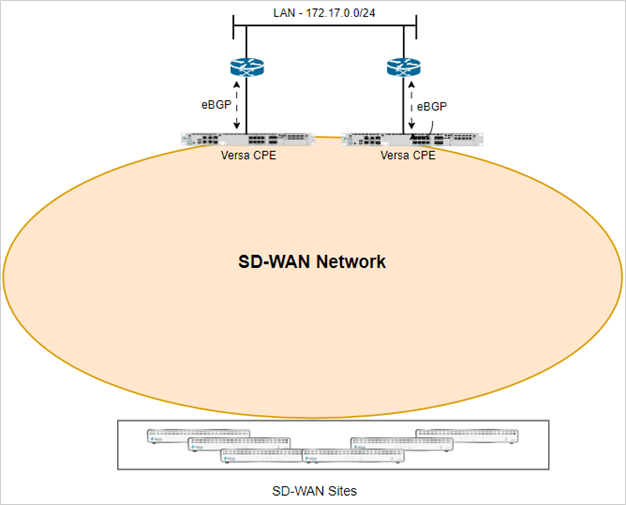
The above topology shows an SD-WAN network where more than one CPE is advertising the same anycast IP prefix. All prefixes from each CPE in the SD-WAN network are exchanged using iBGP through the Versa Controller which functions as a BGP route-reflector. On the LAN of the CPE’s, there is an eBGP session configured to the network peer device for dynamic route exchange of the LAN and SD-WAN VPN prefixes.
The Versa CPE’s that advertise these anycast prefixes are typically placed in the primary Datacenter and redundant Datacenter connected through an internal network. It can also be a Versa VM in a public or private cloud installation where the same prefix is advertised from multiple cloud regions or landing zones connected through the cloud providers network.
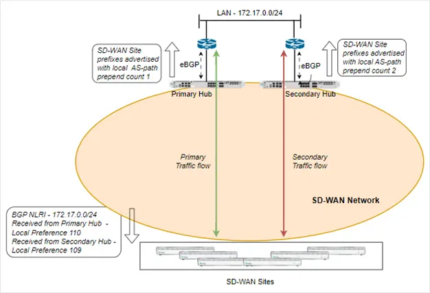
In a full mesh network scenario, if the hub site is configured in High Availability mode, then the primary device advertises the anycast prefix into the SD-WAN network using iBGP with a higher local preference than the peer device. In the case of a Hub-Spoke network design, the hub priority configured in the spoke group creates a configuration on the spoke site that sets a higher local preference for routes received from the higher priority hubs. On the LAN side, the primary CPE advertises the SD-WAN prefixes with a lower AS path than the secondary CPE, this causes the peer device to choose the primary CPE as its preferred next hop.
In this article, we will refer to the CPE’s that advertise anycast prefixes as Hub CPE’s.
In the case of next-hop selection using an SD-WAN traffic steering policy, the administrator can create a traffic steering policy rule on the spoke sites to select the next-hop based on a configured priority. Each next-hop can be tied to an SLA profile that uses an SaaS App monitor configuration to measure the SLA’s to a remote FQDN or IP address.
Use case for SLA based Routing
When the two hub CPE’s are in the same premise and share the same WAN paths, then the static routing metric based path selection or SD-WAN traffic steering policy based next-hop selection works fine due to their shared fate, which is the WAN path. A deterioration in WAN path metrics will affect both the CPE’s and only in cases where the primary hub CPE is unreachable or if there is a failure on the LAN side of the primary CPE does the switchover to the secondary CPE happen. When this happens, the eBGP connection from the primary hub CPE to the peer on the LAN is terminated which causes the return traffic from the hub LAN to stop using the primary CPE but choose the secondary hub CPE instead. This ensures a symmetric flow over the SD-WAN network.
There are scenarios such as when the primary hub CPE and secondary hub CPE are deployed in different premises with different WAN link connections. These can be two datacenters placed in different geographic locations or it can be a public cloud use cases (AWS, Azure, GCP etc.) where one cloud region subnets are advertised from multiple other regions or cloud landing zones.
SLA based Routing
When more than one CPE is advertising the same network prefix, it is possible that the SLA metrics to the primary hub CPE have deteriorated from the remote site and the failover of traffic should happen to the next chosen CPE. This change needs to be communicated to the routing domain so the remote spokes will change the metrics of the received anycast network prefix to choose the next priority hub. Similarly, the hub’s need to alter the metrics of the prefixes advertised into the LAN network so that the return traffic from the LAN goes to the currently preferred SD-WAN Hub. All of this needs to happen automatically without any interference from the administrator.
This feature is referred to as SLA-based Routing and is available on VOS software version 22.1.3 onwards.
Network Topology
Let’s consider a cloud use case scenario where the VOS VM is installed in two Azure regions – North Europe and West US. The North Europe region has a VNET with workloads in them. The VNET routes are advertised into the SD-WAN network through the VOS VMs using the Microsoft Azure vWAN service. Two vWAN hubs are installed in the two Azure regions and there is a BGP peering with the local VOS VMs. The Azure hub in North Europe advertises the destination VNET prefix to both the Versa VMs in North Europe and West US. Similarly, the Versa SD-WAN spoke network prefixes are advertised to the Azure vWAN hubs from both the Versa VOS VMs installed in the two regions.
If the traffic enters the Azure network via the west US region, then the Microsoft private backbone is used for inter-region transit. The intent is to have the remote sites choose the best region depending on the SLA metrics. If there is a deterioration in the WAN path to the chosen Azure region, the traffic should be able to failover automatically to the other Azure region.

The remote site CPE is in the west US region. From a latency perspective, the Azure region west US is closer to the remote site than the north Europe region.
Note that this scenario can also be extended to other cloud providers and on-premise deployments.
Configuration
Step 1:
Configure a SaaS App Monitor probe with the same name is in each of the Versa hub VM’s configured in the Azure north Europe and west US region. The SaaS App Monitor will probe an application IP address in the destination VNET in Azure north Europe region.
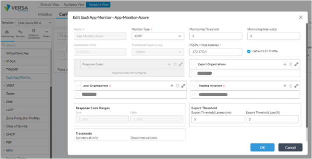
Note: In the Export Organization and Local Organization, put in the tenant name. In the Routing Instance, enter the LAN VRF from where this destination IP address is reachable.
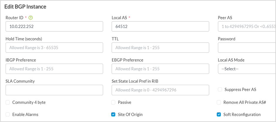
Step 2:
On the remote site CPE, in the <Tenant-name>-Control-VR, edit the default BGP instance and enable the following option
- Site Of Origin
- Soft Reconfiguration
Step 3:
1. Navigate to the SLA Profile section in the BGP instance of the <Tenant-name>-Control-VR where a new SLA Profile needs to be created.
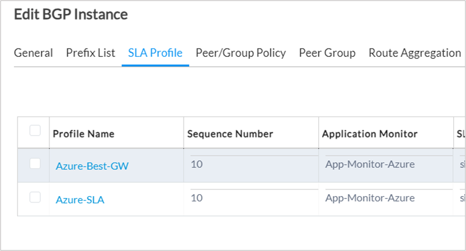
2. Create a new SLA Profile.
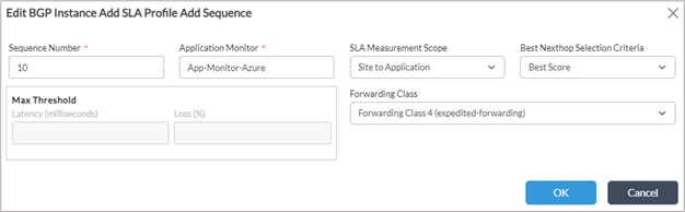
3. Enter any sequence number.
4. The Application Monitor refers to the SaaS App Monitor created on the hub. The same name should be used here.
5. The SLA Measurement Scope have the following options
- Site to Gateway – The SLA path measurements of all the WAN paths from the local device to the remote hub.
- Gateway to Application – The SLA path measurements from the Hub to the polled IP address in the destination VNET using the SaaS App Monitor. This SLA value is exported from the hub to the local site.
- Site to Application – The SLA path measurement from the local site to the polled IP address in the destination VNET from the hub on each of the WAN paths. This value is got by combining the SLA measurement from the local site to the hub and the SLA measurement from the SaaS App Monitor received from the hub.
6. The Next Selection Criteria can be the following option
- Left blank – If left blank then the max latency and loss values can be filled. If the primary path exceeds this value, the failover to the alternate path happens.
- Least Packet Loss – Select the path with the least packet loss
- Least Latency – Select the path with the least latency
- Best Score – Score is computed based on the packet loss and latency.
7. Note that in this configuration example, we will choose the Best Score as the Next Selection Criteria.
8. Forwarding Class – Select FC4 which is the default class on which branch to branch SLA’s are also sent.
9. More than one sequence can be added to the SLA profile for different Application Monitors configured on the hub.
Step 4:
1. In the BGP instance of the <Tenant-Name>-Control-VR, add a new term to the TO_SDWAN Peer/Group Policy. Ensure that this term is the first term in the policy.
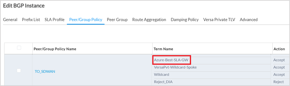
2. In the Match conditions, add the following configuration
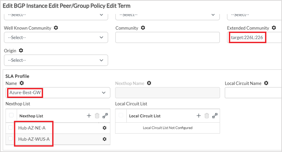
- Extended Community: target:<VRF-id>L:<VRF-id>, where the VRF-id can be obtained from the <Tenant>-LAN-VR configuration.
- SLA Profile Name: Select the SLA Profile created earlier.
- Nexthop Name: If only one next-hop hub should be allowed for selection. This field is optional and can be left blank.
- Nexthop List: List the next-hop hubs to be allowed for selection. This field is optional and can be left blank. If left blank, then all possible next hops from which the anycast route is received will be added to the list.
- Local Circuit Name: List the local circuit name to only be allowed for selection. This field is optional and can be left blank.
- Local Circuit List: List the list of local circuit names to only be allowed for selection. This field is optional and if left blank then all local circuits whose SLA towards the Hub is UP will be included.
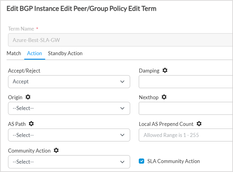
3. In the Action tab, enable the SLA Community Action option.
Step 5:
1. Edit the T-Direct, T-Static, T-OSPF , T-BGP terms in the redistribution policy of the <Tenant-Name>-LAN-VR VRF.
Note that the Static, OSPF and BGP terms are optional and only present if these protocols have been configured. The starting letter T is usually prefixed by a number like T2-Direct and T3-Static.
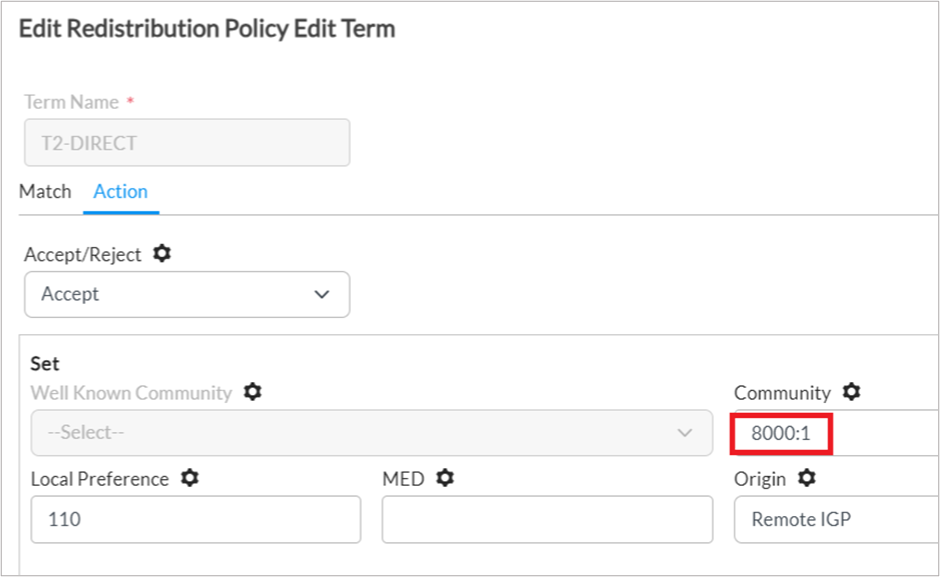
2. Remove the existing value in the Community field and replace with 8000:1. Repeat this for the other terms in the policy.
Step 6:
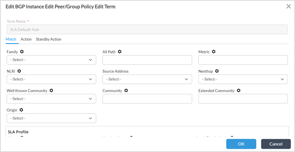
1. Add two terms in the BGP “Import-From-Hub-Policy” in the order as shown in the picture. Note that this policy only exists if the site is configured as a spoke site. If it is a full mesh site, then the “Import-From-SDWAN-Policy” needs to be edited.
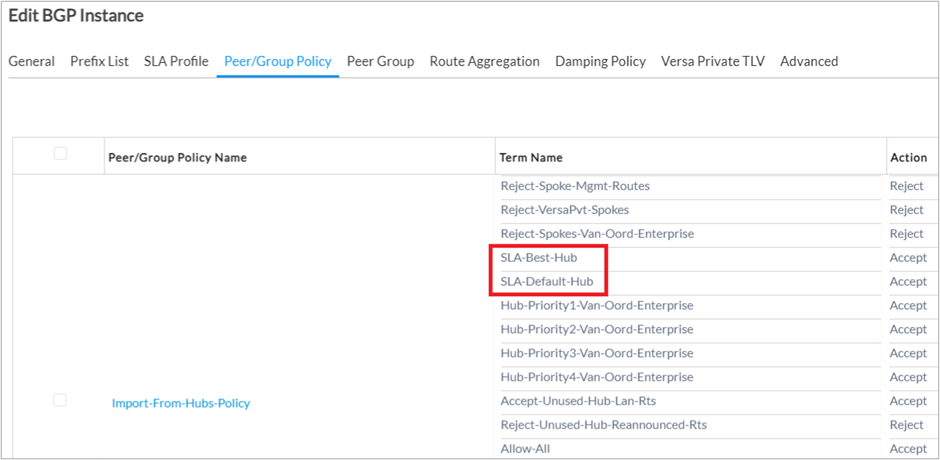
2. In the term “SLA-Best-Hub”, add the following configuration.
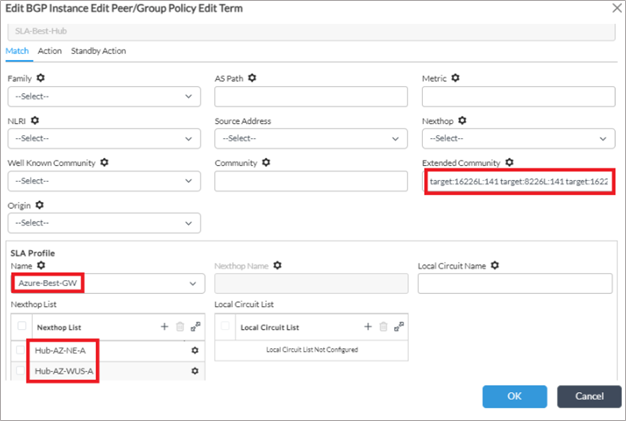
- The extended community should have the community values for each of the hub CPE’s in the below format. These values can be taken from the import and export RT configuration in the <Tenant>-LAN-VR.
– target:8<tenant-id>:<VRF-id> target:16<Tenant-id>:<site-id>
- So if there are 2 hubs, then 4 community values should be added. Leave a space after each community value.
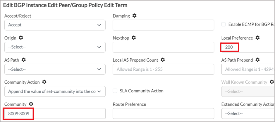
3. Set the set action in this term as follows.
- Local Preference is set to 200
- Community is set to 8009:8009
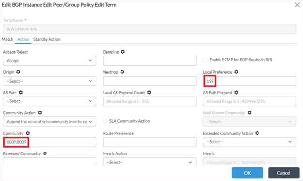
4. For the second term “SLA-Default-Hub”, leave the Match conditions blank and set the local preference to 199 and community to 8009:8009.
Verification
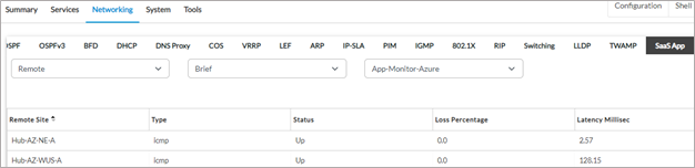
1. The metrics collected from SaaS App Monitor probe on the two hub CPE’s. Note that this probe is configured on the hub CPE and is exported to other sites in the SD-WAN network.
The output below is taken from the remote spoke site and hence the Remote option is selected since the probe is not locally configured.
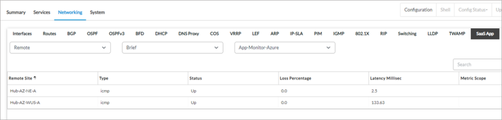
As seen, the Hub Hub-AZ-NE-A has a very low latency because this VOS VM is in the same Microsoft region (north Europe) as the application. The Hub-AZ-WUS-A has a higher latency because it is in another region (west US). The SLA metrics measured from the Hub-AZ-WUS-A includes the latency over the Microsoft Azure private backbone network.
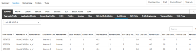
2. The SLA metrics from the spoke towards both the Hub devices.
To Hub Hub-AZ-NE-A
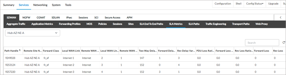
To Hub-AZ-WUS-A
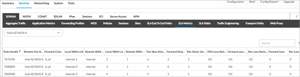
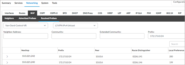
3. The spoke site has the primary route pointing towards the Hub Hub-AZ-WUS-A even though this hub is not in the same region as the destination VNET. The reason is that the path metrics, especially the latency from the spoke site to this hub, plus the metrics from the hub to the application is lower than the same path through the local region hub.
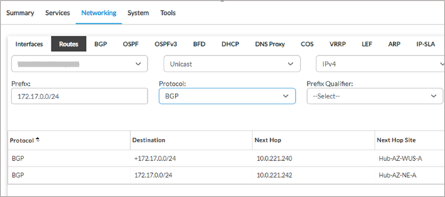
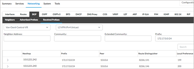
4. The route learnt from Hub-AZ-WUS-A is primary because this route has been received with a local preference of 200. This value of 200 was set in the “SLA-Best-Hub” term in the “Import-From-Hub-Policy” in the BGP instance of the <Tenant-name>-Control-VR (refer step 6 in the configuration above).
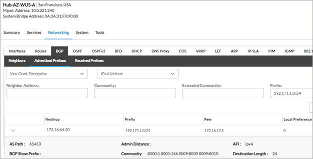
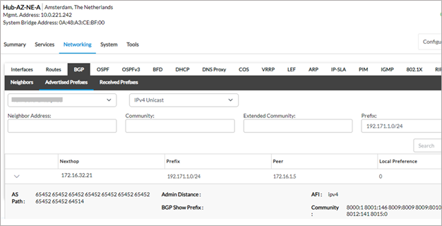
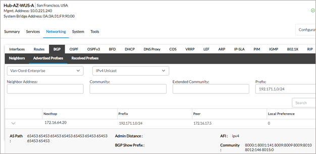
5. On the Hub CPE’s, the LAN route of the spoke CPE is advertised to the Azure vWAN service with different AS paths.
Since the Hub-AZ-WUS-A is the primary next hop chosen, this router advertises the spoke LAN prefixes with a lower AS path compared to the other hub. This ensures that all traffic sourced from the Azure VNET subnet 172.17.0.0/24 to the destination spoke LAN subnet 192.171.1.0/24 traverses this region hub by transiting the Microsoft backbone network.
From Hub-AZ-WUS-A
From Hub-AZ-NE-A
6. To verify the behavior when the next hop changes due to a path deterioration, a WAN emulator is used to introduce latency on the path from the site to the hub site Hub-AZ-WUS-A. As seen below, a latency of 400m sec is added on all the WAN paths to this hub.
The metrics to Hub-AZ-NE-A have not changed.

The metrics to the application from the Hub sites as measured by SaaS application monitor have also not changed.
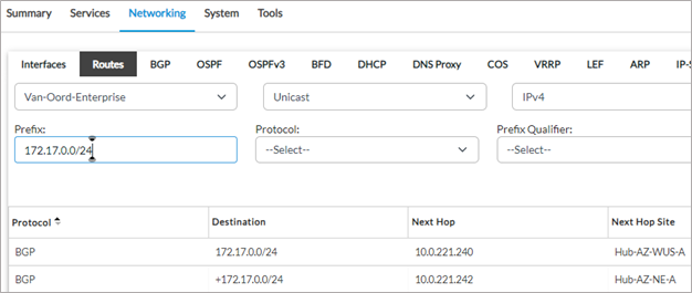
7. The routing table on the spoke site has now been updated. The primary next hop for the Azure VNET 172.17.0.0/24 is now through the Hub-AZ-NE-A.
The next hop has changed because the local preference set on the spoke site for prefixes received from the Hub-AZ-NE-A is 200 and it is 199 for the other hub.
8. On the Hub-AZ-NE-A, the spoke site route 192.171.1.0/24 is advertised to the Azure vWAN hub with a shorter AS path when compared to the other Versa hub. This causes the Azure network to prefer the Hub Hub-AZ-NE-A for the traffic destined to the remote spoke. This ensures that the forward and reverse path of the traffic is through the same Versa hub VM.
From Hub-AZ-WUS-A
From Hub-AZ-NE-A
Notes
1. This feature requires VOS software version 22.1.3.
2. SD-WAN traffic steering policies to set the path priorities to the hub can be used along with this feature.
3. This feature also works with SD-WAN traffic engineering where the path through a remote next hop can traverse multiple next hops. This is because the per-path SLA’s are exported to other devices in the SD-WAN network, allowing each CPE to build a database of the network with end to end SLA measurements.
4. This feature also works when OSPF is used as the LAN routing protocol.
Conclusion
The SLA based routing feature allows the remote sites to choose a hub in real-time based on the SLA metrics. Since the SLA information is fed into the routing domain, the LAN network on the hub, which is outside the SD-WAN domain is able to learn of the hub priorities through changes in BGP path attributes.
In any network design, traffic symmetricity is important so that security inspection can be applied to this traffic and detailed application statistics is available to view in Analytics because the application traffic can be properly identified by the Versa DPI module.


