Deploying SD-WAN sites with Aggregate Ethernet LAN Interfaces
by Andrey Bazovkin and Arjun Sethuraman
Introduction
VOS allows using Aggregate Ethernet interfaces (802.3ad) for LAN connectivity on SD-WAN routers with LACP or static bundling. General considerations for Aggregate Ethernet use cases are the following:
- All interfaces in a bundle must be configured for full-duplex, have the same speed setting, and have the same physical layer.
- It’s highly recommended to have the number of interfaces in a bundle, which is a power of 2, to have more even traffic distribution.
- Depending on LAN side device capabilities, it’s recommended to use Link Aggregation Control Protocol (LACP) to negotiate an automatic bundling of interfaces over a static bundling setup.
Configuration
Step 1: Workflow template creation
To create an SD-WAN branch with Aggregate Ethernet LAN interfaces, you must create a branch workflow with single or multiple LAN interfaces.
If you already have a workflow template, skip to Step 2, “Device template modification”.
If you have a trunk interface on the LAN side and want to create several LAN Networks, you can do it here by clicking on the ‘Add Sub Interface’ option.
Fill in the subsequent tabs in the workflow template and click ‘
Deploy’ to deploy the template.
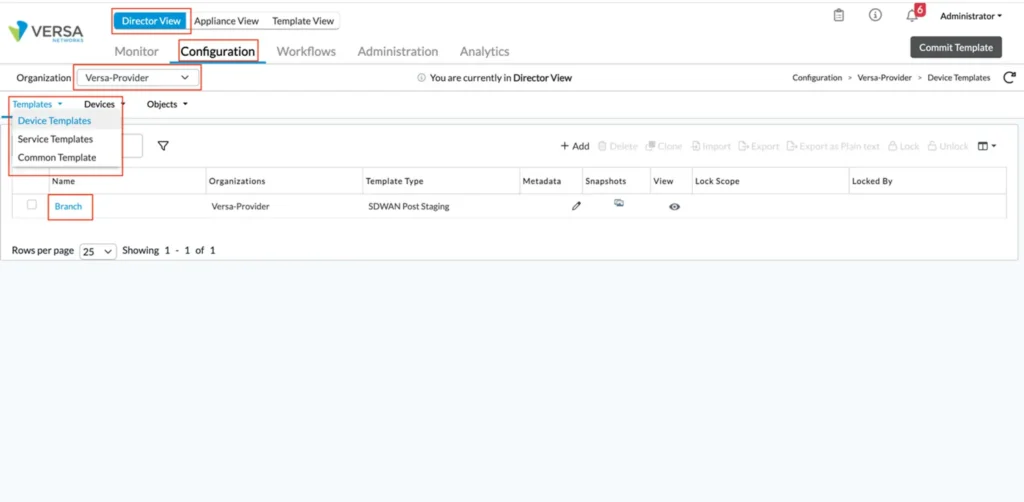
Step 2: Device template modification
In the Director view, click on Configuration, choose the appropriate organization and click on Templates > Device Templates.
Click on the Template that you want to Modify. In this case, it is the template ‘Branch.’
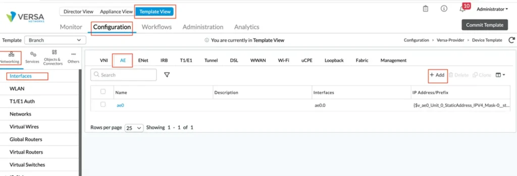
Step 3: Configure a new aggregate ethernet interface
In the template configuration, navigate to the Networking > Interfaces > AE tab and click ‘
+ Add’ to add a new Aggregate Ethernet interface.
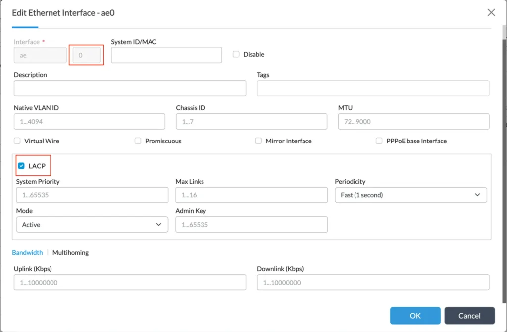
Enter the Aggregate Ethernet interface number and enable LACP (if required). Default LACP parameters should fit the majority of cases. However, if needed, you can adjust System Priority, Max Links, Periodicity (slow/fast), Mode (active/passive). Click on ‘Ok’ to apply the setting.
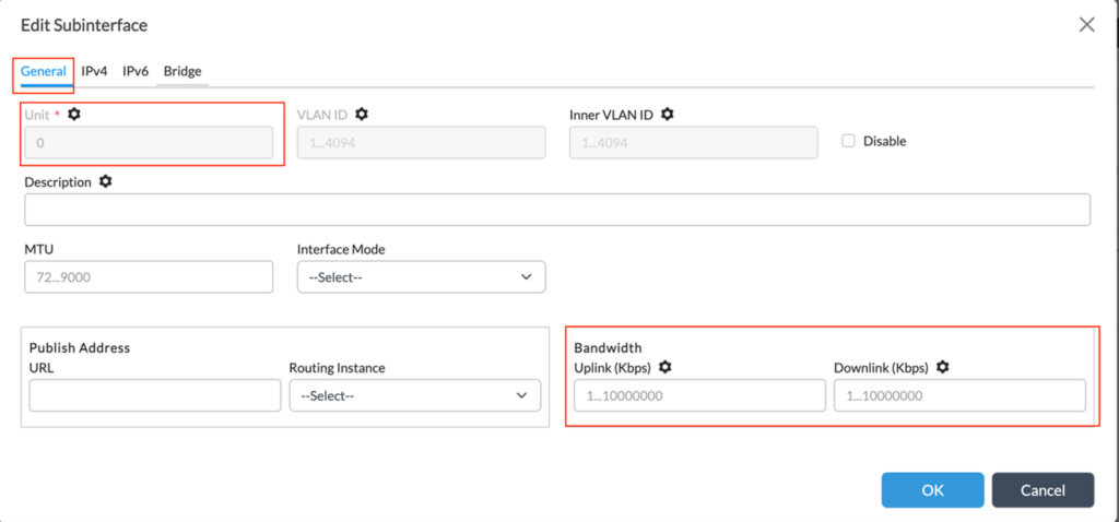
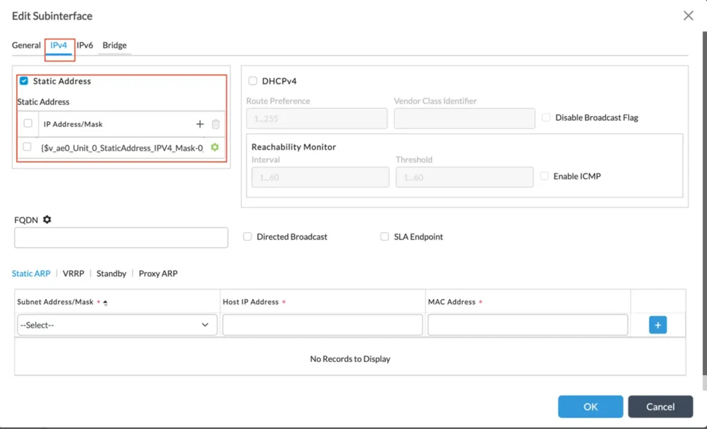
In the Sub Interfaces tab, click on ‘+’ to add the interface details. Add IP address for (each) sub-interface – you may also want to parameterize it using the “gear” button. If this is a non-trunk interface, we can select Unit number ‘0’; for all other cases select unit numbers 1-4095 and fill corresponding VLAN ID.
If you have VRRP configured on the LAN side, you need to reproduce its configuration on the corresponding tab of sub-interface configuration. You can copy those data from existing LAN interface configurations. By default, if generated by workflow, Group ID would be 1, priority 200 for primary router and 150 for secondary with preempt enabled.
Optionally you may need to check the Speed/Duplex configuration on this screen in the “Others” section. All interfaces in a bundle must be configured for full-duplex and the same.
Step 4: Interfaces Modification
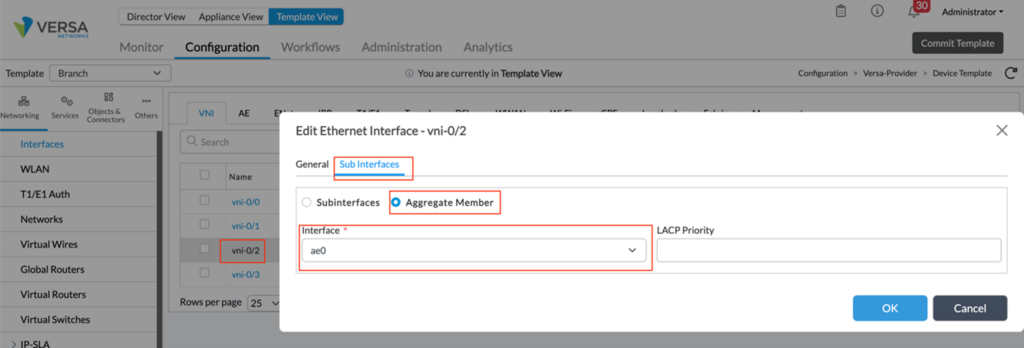
Select the LAN interfaces that will be part of the aggregate ethernet and assign them to the group. Click on Interfaces > ‘Interface’ > Sub Interfaces, choose ‘Aggregate Member’, and select the aggregate interface created in Step 3.
Repeat this step for all the interfaces that are a part of the aggregate ethernet. In this case, we do it for vni-0/2 and vni-0/3.
Step 4: Networks Modification
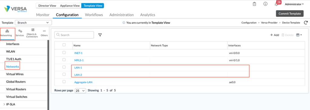
Navigate to the Networks section under the Networking tab and remove the association of the LAN interfaces from the LAN networks. In this case, vni-0/2 and vni-0/3 associated with the networks LAN-1 and LAN-2 have been removed.
Add the aggregate ethernet interface to the LAN-VR of the Tenant under Virtual routers.
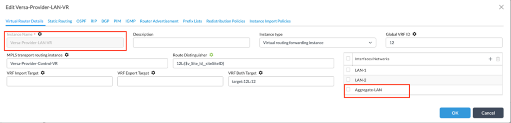
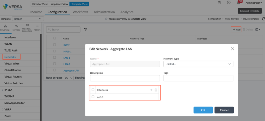
Navigate to the Networks and click ‘+ Add’ to add a new Network. Make the aggregate ethernet interface ae0.0 part of this network.
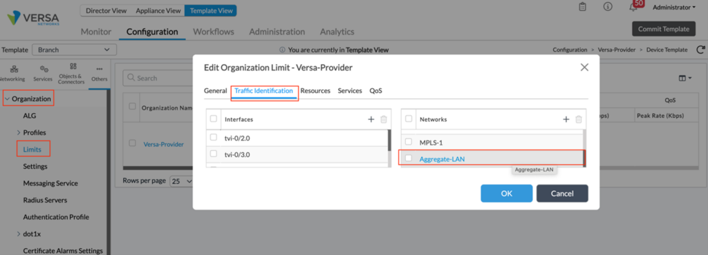
Step 5: Modifying Organization Limits
Under organization limits, add the newly created network – ‘Aggregate-LAN’ under Traffic Identification.
Also, remove the interfaces vni-0/2 and vni-0/3 from under the interfaces tab.
Step 6: Modifying VNF Manager
To modify the VNF manager, click Others > System > Configuration > Configuration. Under the configuration tab, click edit VNF manager and add the aggregate ethernet interface to the list of interfaces.
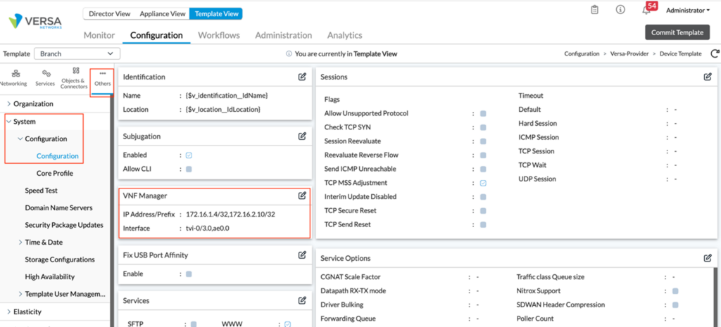
This completes the new Aggregate Ethernet interface configuration.
Additional notes
- If you have a non-standard DHCP Server or Relay configuration bound to a LAN interface instead of a LAN Network (how workflow creates it), then you need to update it accordingly
- If you have IP-SLA Monitor using the LAN interface as a source, you must change this source to the new ae0/x interface. (available starting from 21.2 releases only)
- QoS shaping and/or DSCP rewrite features are not supported on Aggregate Ethernet interfaces in the current 21.2 VOS release.
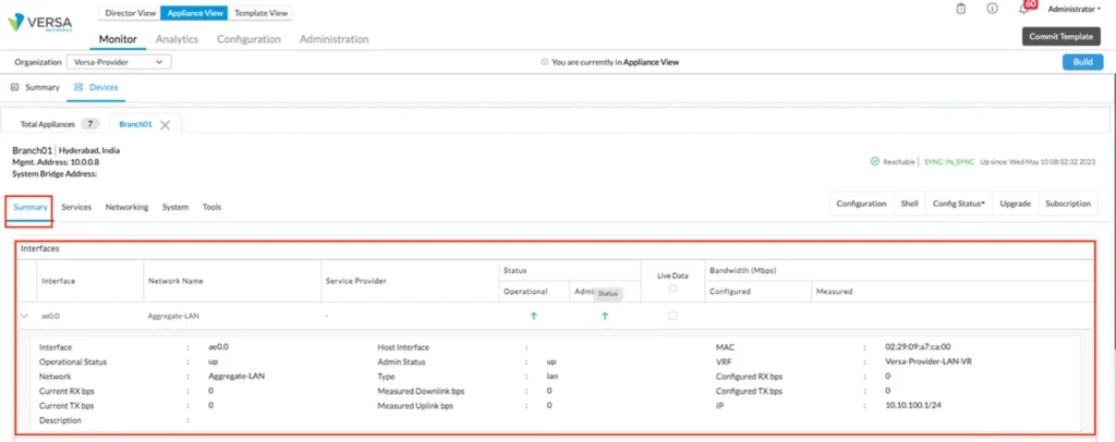
Aggregate Ethernet interface Verification
Aggregate Ethernet interface basic statistics can be seen similarly to other interfaces on VOS device, and more detailed information is available from device cli using the ‘show aggregate-ethernet’ command.
admin@Branch01-cli> show aggregate-ethernet

Flags: D:Down U:Up d:Disabled
       I:Individual S:Standby P:ProtoDown

 AE-NAME   STATUS   PROTOCOL    MEMBERS
--------- -------- ---------- ------------------
  ae0        up        LACP       [ vni-0/2(U) vni-0/3(U) ]

[ok][2023-05-11 04:15:03]
admin@Branch01-cli>
Additional LACP statistics are available via ‘show lacp info interfaces’ and ‘show lacp statistics’ cli commands:
admin@Branch01-cli> show lacp info interfaces
AE    MEMBER            SYSTEM                    PORT      PORT    PORT
NAME  INTF     ROLE     PRIORITY  SYSTEM ID       PRIORITY  NUMBER  KEY
--------------------------------------------------------------------------
ae0   vni-0/2  Partner  127       2:29:9:a7:ca:0  127       2       992
ae0   vni-0/2  Actor    127       2:29:9:a7:ca:0  127       2       992
ae0   vni-0/3  Partner  127       2:29:9:a7:ca:0  127       3       992
ae0   vni-0/3  Actor    127       2:29:9:a7:ca:0  127       3       992


admin@Branch01-cli> show lacp statistics
                                                                  LACP      LACP
                             LACP   LACP   LACP   LACP    LACP    MARKER    MARKER    LACP     LACP
AE    MEMBER   LACP   LACP   RX     PDU    PDU    MARKER  MARKER  RESPONSE  RESPONSE  UNKNOWN  ILLEGAL
NAME  INTF     RX     TX     ERROR  RX     TX     RX      TX      RX        TX        RX       RX
--------------------------------------------------------------------------------------------------------
ae0   vni-0/2  69742  69666  0      69742  69666  18      21      11        18        0        10
ae0   vni-0/3  69742  69666  0      69742  69666  18      21      11        18        0        10

[ok][2023-05-11 04:18:01]
admin@Branch01-cli>
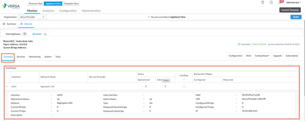
We can view the aggregate interface status from the monitor tab, as shown below.
Summary
In this article, we have understood the steps to create an Aggregate Ethernet LAN interface to the SD-WAN branch and the eventual changes needed in the Device template to accomplish this.


