The purpose of this article is to show how to optimize traffic sent to ZScaler cloud using active probes and measuring SLA parameters to influence DIA traffic steering. ZScaler recommends configuring two separate GRE tunnels to two ZIA Public Service Edges that are each located in a different data center for high availability. To perform service monitoring, Layer 7 (HTTP kind) health checks should be deployed. Alternatively, Layer 4 health checks, such as ICMP could be used. ZScaler provide URLs(servers) to perform HTTP Raw Request in the bellow form:
http://gateway..net/vpntest
Figure 1 shows a topology which is mirroring the ZScaler Architecture.
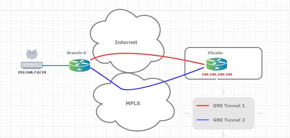
Here, Branch-6 uses 2 transport domains (Internet & MPLS) to connect to ZScaler cloud. Over each transport domain a GRE tunnel is built between the VOS device and the ZScaler cloud: GRE tunnel 1 over Internet and GRE tunnel 2 over MPLS. 100.100.100.100 on the ZScaler side will be used as a destination for probes sent over the two tunnels (Transport Domains). Based on probes collected data the appliance will decide on which tunnel the traffic will be sent.
The probe allows for monitoring of a specific FQDN (via either ICMP, HTTP, or TCP) and then calculates a delay and loss value. This FQDN can be any that is exposed to the internet and associated with the customers SaaS service. A threshold for packet delay and loss can then be assigned and any path falling outside of that threshold can be marked as ‘sla violated’ and taken out of forwarding path. Only the new sessions will avoid the non-compliant SLA path. The existing sessions will remain on it. In addition, the path with the better delay and loss could be used to steer the application traffic. Active monitoring is especially useful when a customer has a mission critical application tied to a specific FQDN. ZScaler will perform SNAT to allow Internet connectivity for users served by the VOS device.
Figure 2 shows the VOS device internal routing instances construct and helps to understand a packet walkthrough (including traffic steering) toward the ZCaler cloud.
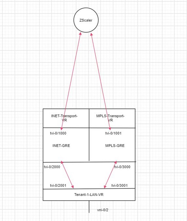
As you can see, two new routing instances are configured INET-GRE and MPLS-GRE.
INET-GRE routing instance has two main interfaces:
– tvi-0/1000 – GRE tunnel toward ZScaler cloud (using Internet transport domain)
– tvi-0/2000 – tvi-pair to connected to the LAN-VR
MPLS-GRE routing instance has two main interfaces:
– tvi-0/1001 – GRE tunnel toward ZScaler cloud (using MPLS transport domain)
– tvi-0/3000 – tvi-pair to connected to the LAN-VR
admin@Branch6-T1-cli> show interfaces brief | match INET-GRE
tvi-0/1000.0 n/a up up 2 INET-GRE 10.10.10.22/30
tvi-0/2000.0 n/a up up 2 INET-GRE 169.254.0.6/31
admin@Branch6-T1-cli> show interfaces brief | match MPLS-GRE
tvi-0/1001.0 n/a up up 2 MPLS-GRE 10.10.10.26/30
tvi-0/3000.0 n/a up up 2 MPLS-GRE 169.254.0.8/31
From routing perspective:
INET-GRE routing instance has two static routes:
– 0/0 via ZScaler GRE tunnel
– LAN VR prefix via tvi-0/2000
MPLS-GRE routing instance has two static routes:
– 0/0 via ZScaler GRE tunnel
– LAN VR prefix via tvi-0/3000
admin@Branch6-T1-cli> show configuration routing-instances INET-GRE routing-options | display set
set routing-instances INET-GRE routing-options static route 0.0.0.0/0 10.10.10.21 tvi-0/1000.0 preference 1
set routing-instances INET-GRE routing-options static route 192.168.7.0/24 169.254.0.7 tvi-0/2000.0 preference 1
admin@Branch6-T1-cli> show configuration routing-instances MPLS-GRE routing-options | display set
set routing-instances MPLS-GRE routing-options static route 0.0.0.0/0 10.10.10.25 tvi-0/1001.0 preference 1
set routing-instances MPLS-GRE routing-options static route 192.168.7.0/24 169.254.0.9 tvi-0/3000.0 preference 1
Lets see how a packet is routing using this architecture:
1. Packet arrives at the LAN-VR
2. SD-WAN policy (configured with the desired granularity) is sending the packet using PBF to one of the two GR routing instances (INET or GRE). The PBF decision is based on the probe’s measurements and configured SLA (packet loss and/or latency) thresholds.
3. Routing lookup happens in respective GRE routing instance and packet is sent over the ZScaler tunnel interface.
4. ZScaler infra is performing the security functions and SNAT and sent the packet to the destination.
The return packet is using the same steps in reverse order:
1. Packet arrives from the Internet to the ZScaler infra.
2. ZScaler infra checks the NAT table, performs the DNAT operation and send the packet toward the appliance over the respective GRE tunnel.
3. VOS appliance performs route lookup and sends the packet over the tvi pair toward the LAN-VR.
4. ARP lookup or routing lookup is performed in the LAN-VR and as a result the packet is sent to the destination.
Let’s see now how to configure this feature and check its functionality.
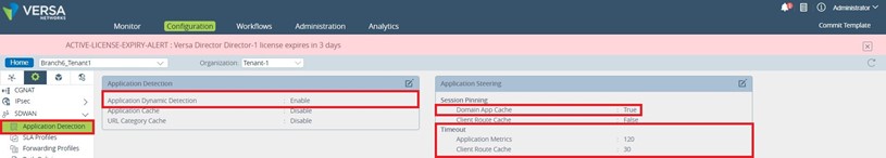
1. The first step is to enable “Application Detection” and “Application Steering” in the respective device template:
2. SaaS Application Monitoring Configuration.
Here is the place to configure the probes which are actively sent by the VOS device toward a FQDN. The configuration path is Device Template – – – > Networking – – -> SaaS App Monitor. We are configuring a ZS (ZScaler) App Monitor which will send PDU probes over the ZScaler GRE tunnels toward a destination in the ZScaler cloud. Based on the collected data the SD-WAN PBF will take a decision regarding on which tunnel the session will be pinned.
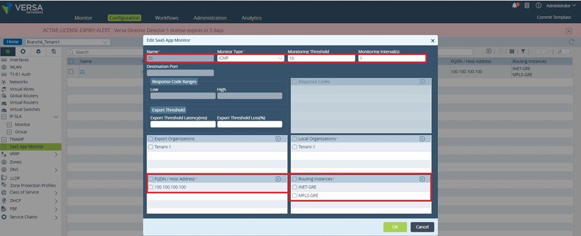
Regarding the fields filed in on the above figure:
Monitor Type:
ICMP: ICMP probe type simply sends an ICMP request to the FQDN, and if a response is received the probe is marked as up, and a measurement is taken.
TCP: TCP probes requires that a TCP handshake is completed over a defined port to the FQDN. If the handshake completes, the probe is marked as up, and a measurement is taken.
HTTP: HTTP probe will send a HTTP GET message to the FQDN, if the response contains a valid, predefined response code, the probe is marked as up, and a measurement is taken.
For simplicity, in our example ICMP probes are used.
Monitoring Interval: The time interval between two consecutive probes
Export Orgs: For CPE’s acting as a Hub and are multitenant, the ORG that the Hub will export information for – not relevant in this case
Local Orgs: For multitenant deployments, which ORG the monitor is for–Tenant-1 is used in this case
FQDN: Any FQDN associated with the customers SaaS service that is reachable from the Versa CPE. 100.100.100.100 is reachable via both ZScaler GRE tunnels
Routing Instance: The routing instance the probe is initiated from. PDU probes are sent in both GRE routing instances over the respective GRE tunnels.
3. Create an SLA Profile to define the threshold for traffic steering. The previously created SaaS application monitoring configuration will be attached to this SLA Profile. The path to create the SLA Profile is Services – – -> SDWAN – – ->SLA Profiles.
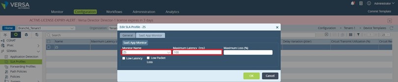
We’ve configured 100ms Maximum Latency to trigger traffic steering for new sessions.
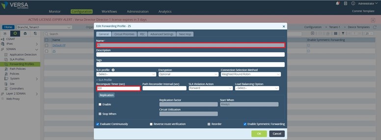
4. Create a Forwarding Profile
With Versa 20.2.X, the legacy policy based forwarding functionality has been integrated into the SDWAN traffic forwarding profiles, called by a common SDWAN policy. This makes for a simpler management experience as well as enables the ability to steer traffic seamlessly between SDWAN attached sites and local internet break-outs. The path to create a Forwarding Profile is Services – – -> SDWAN – – ->Forwarding Profiles. The PBF functionality is found under the ‘Next Hop’ tab on the SDWAN forwarding profile. We’ll create a Forwarding Profile named “ZS” with a recompute time of 300sec and two “Next Hops”: one using INET-GRE routing instance, the other MPLS-GRE routing instance.
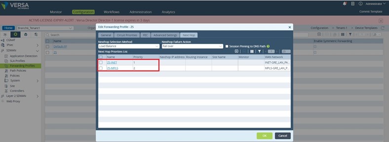
As it can be seen in the figure above the ZS-INET NextHop has a better priority than ZS-MPLS NextHop, 1 versus 2. So, as long the path is SLA compliant the traffic/sessions will be policy routed toward INET-GRE routing instance, practically using the ZScaler Internet transport GRE tunnel – tvi-0/1000 (refer to Figure 2). When the primary path goes out of compliance the new sessions will be policy routed to the ZS-MPLS NextHop which uses the second ZScaler GRE tunnel – tvi-0/1001. Let’s see now how the two next hops are configured.
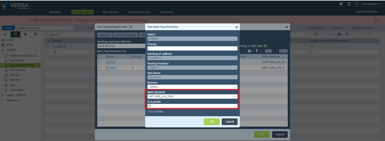

As it can be seen both NextHops are referencing the previously configured “ZS” SLA profile. Regarding the “WAN Network” the ZS-INET NH is using INET-GRE_LAN_PAIR and ZS-MPLS NH is using MPLS-GRE_LAN_PAIR. As you probably already realized these “WAN Networks” are the tvi pairs between the LAN-VR and the two routing instances used for building the GRE tunnels toward ZScaler: INET-GRE and MPLS-GRE.
set networks INET-GRE_LAN_PAIR interfaces [ tvi-0/2000.0 ]
set networks MPLS-GRE_LAN_PAIR interfaces [ tvi-0/3000.0 ]
5. Create the SDWAN Policy Rule.
The SWAN Policy Rule is the final step in configuring the required functionality. The Policy Rule could be very granular regarding the matched traffic and it will reference the previously configured Forwarding Profile to implement the desired Policy based forwarding. The configuration path is Services – – -> SDWAN – – -> Policies – – -> Default-Policy – – -> Rules.
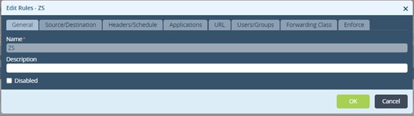
A single rule will be created for this example: “ZS”
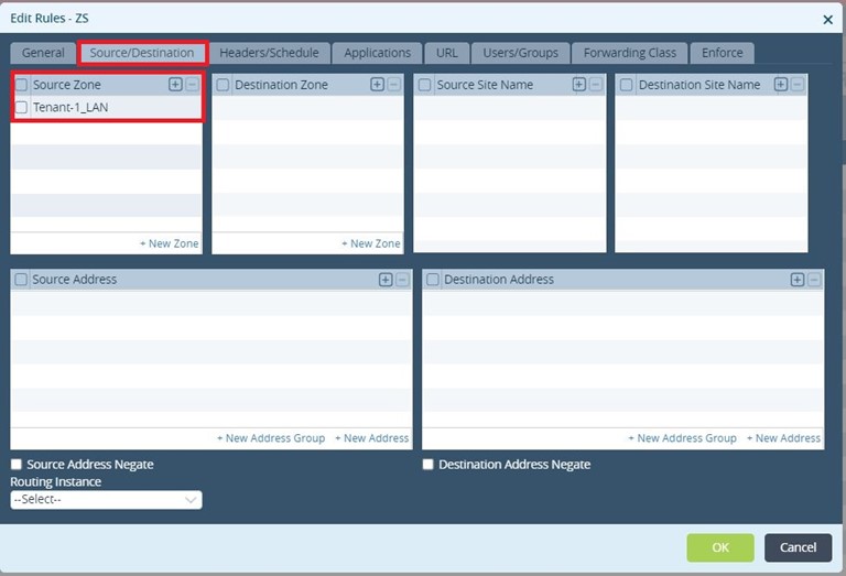
The interesting traffic is the one coming from the LAN-VR (Source Zone = Tenant-1_LAN). We would not use any other traffic matching criteria as We like the traffic to use one of the two ZScaler tunnels irrespective of its type.
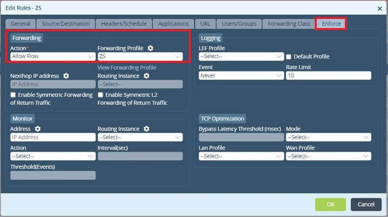
The last step is to enforce the PBF/Forwarding Profile.
Let’s verify the functionality.
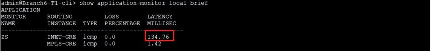
We’ll use the bellow command to check the loss and latency values gathered by the SaaS Application Monitor.
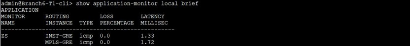
As you can see both paths/GRE tunnels are SLA Compliant.
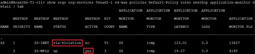
Let’s check now what is the status of the two NextHops used by SDWAN PBF.
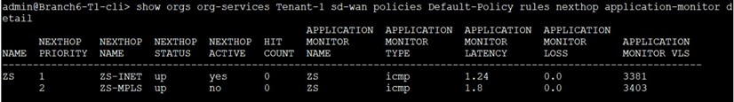
Both NextHops are in “up” state and ZS-INET is the “active” one as it is SLA compliant (latency less than 100msec) and has better priority compared with ZS-MPLS NextHop. We start sending traffic (ICMP PDUs) from LAN-VR toward 8.8.8.8.
As it can be seen, there are hits on the ZS-INET NH (active one)
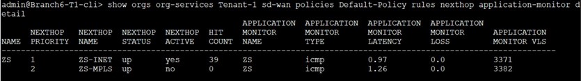
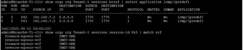
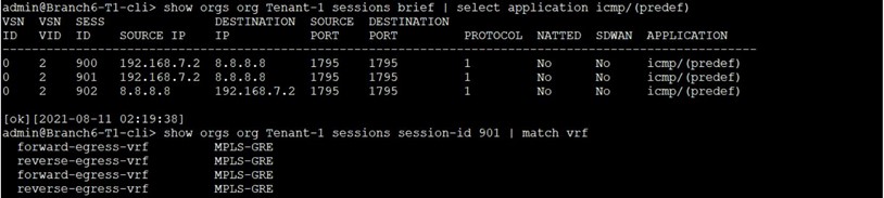
and the traffic is using the INET-GRE ZScaler GRE tunnel:
Now, we’ll try to change the active NextHop by introducing latency on the first/active path.
As a result ZS-INET NextHop is reported as “sla-violated”, and ZS-MPLS NextHop becomes the “Active” one:
Starting to send again ICMP PDUs from the LAN-VR toward 8.8.8.8 We see the traffic is using now the MPLS-GRE ZScaler GRE tunnel.
As an observation, compared with SD-WAN for DIA traffic it is not possible to evaluate the sessions continuously, so the existing session will stay on the SLA non-compliant path. Only the new sessions will use the SLA compliant paths (active NextHops).
Summary
In this article, we saw how steer DIA traffic over different ZScaler GRE tunnels based on active probes sent by a VOS device. For more information regarding SD-WAN PBF feature please consult Versa Networks official documentation.


%20Traffic%20Steering)