Anycast Proximity Deployment
by Maksym Dmitriiev
Use Case Introduction
Rapid changes of modern network technologies, multicloud strategy and security stack transformation accelerate business and keeps market agile in delivering more secure and reliable experience to the end customers. Versa Secure SDWAN solution being an essensial part of SASE architecture framework provides unified connectivity and security for end users, offices, Data Centers, Cloud Native Integration at the same time without limiting technological flexibility demanded in the comprehensive deployment scenario.
Lets consider a use case for the business critical service like internal DNS. The requirement is to have this service distributed across multiple Data Centers or Cloud instances and leverage IPv4 anycast address for simplified end host configuration. To improve user experience consuming this service, the goal of a network administrator is to ensure optimal proximity between offices and hosting locations while keeping geographical redundancy in case of disaster.
Topology Overview
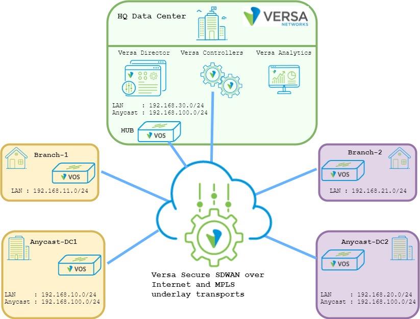
Below topology shows ACME organization that uses Versa Secure SDWAN solution. Company has a Global Data Center acting as a HUB location. For optimal routing and performance ACME uses Spoke-to- Spoke direct topology that allows direct data plane flows between Branches. For the important services ACME has also Local Data Centers in different regions. In the example topology below, Branch-1 and Anycast-DC1 is part of the Orange region while Branch-2 and Anycast-DC2 is part of the Purple region. In all Data Centers which are HUB-DC, Anycast-DC1 and Anycast-DC2 company hosting DNS Anycast servers with IP 192.168.100.10/24.
System Administrator has a requirement to deliver Anycast DNS service to the Branches based on the regional Local Data Center proximity. In case of disaster in the Local Data Center, Branches should failover to the Global Data Center. Important caution is that Branches should never failover to other regional Local Data Centers as the compute resources of the hosted services there are not sized to support extra load outside of its own region.
Picture 1
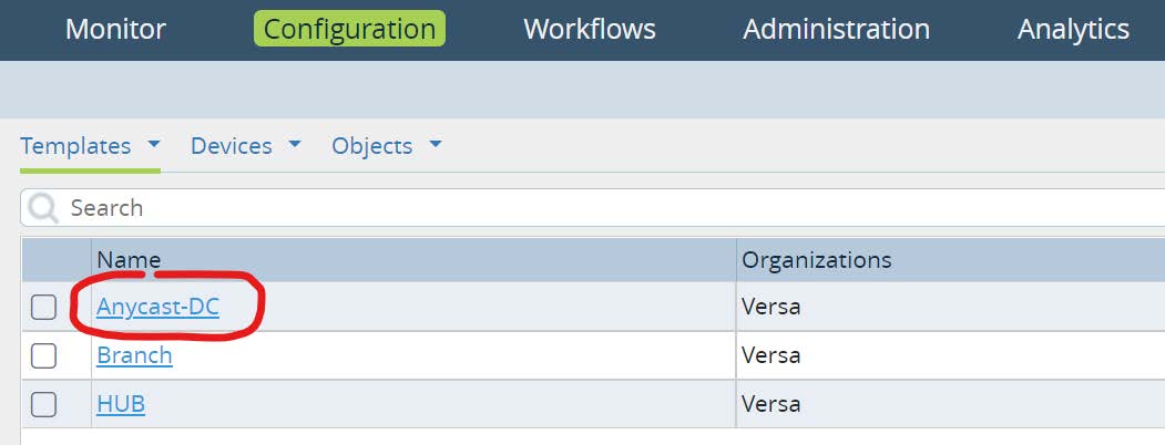
Configuration Steps
As a first step let’s verify the default Spoke-to-Spoke direct implementation and in particular the data flow from Branch-1 and Branch-2 to the Anycast service. To check the routing table of any Branch, from Versa Director UI navigate to
Administration -> Appliances and click on any appliance hostname. Next go to
Monitor -> Services -> Routes and select LAN routing table for unicast IPv4 prefixes.
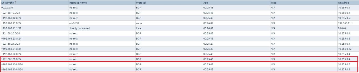
Picture 2
Picture 2 displays output of the LAN routing table at the Branch device. It has 2 active equal path to anycast destination subnet
192.168.100.0/24 with the next hop pointing to Anycast-DC1 and Anycast-DC2. Anycast destination with next hop of the HUB-DC installed as well, but it is not marked as an active route. Lets verify why?
Picture 3 displays output of the SDWAN Control-VR for Anycast destination. As we can see the Anycast subnet has been received from HUB-DC with BGP local preference 101 while from both Local Data Centers it has equal BGP local preference 110. ACME uses spoke-to-spoke direct topology and as a result Branch-1 in Orange region treat the Anycast destination subnet being equal from Anycast-DC1 and Anycast-DC2, but less preferred to the HUB Data Center.
admin@Branch-1-cli> show route table l3vpn.ipv4.unicast routing- instance Versa-Control-VR receive-protocol bgp 192.168.100.0/24 exact

Routes for Routing instance : Versa-Control-VR AFI: ipv4 SAFI:
unicast

Routing entry for 192.168.100.0/24
   Peer Address : 10.255.0.0
   Route Distinguisher: 2L:102
   Next-hop : 10.255.0.6
   VPN Label : 24704
   Local Preference : 110
   AS Path : N/A
   Origin : Igp
   MED : 0
   Community : 8000:1 8001:101 8009:8009 8010:1000
   Extended community : target:2L:2
   Preference : Default
   Weight : 0

Routing entry for 192.168.100.0/24
   Peer Address : 10.255.0.0
   Route Distinguisher: 2L:103
   Next-hop : 10.255.0.8
   VPN Label : 24704
   Local Preference : 110
   AS Path : N/A
   Origin : Igp
   MED : 0
   Community : 8000:1 8001:101 8009:8009 8010:1000
   Extended community : target:2L:2
   Preference : Default
   Weight : 0

Routing entry for 192.168.100.0/24
   Peer Address : 10.255.0.0
   Route Distinguisher: 8002L:101
   Next-hop : 10.255.0.4
   VPN Label : 24704
   Local Preference : 101
   AS Path : N/A
   Origin : Igp
   MED : 0
   Community : 8009:8009 8009:8010 8012:101
   Extended community : target:2L:2 target:8002L:101
   Preference : Default
   Weight : 0

[ok][2021-10-15 05:24:00]
admin@Branch-1-cli>
Picture 3
Based on the default implementation using WorkFlow configuration wizard, DNS requests will be load-balanced between the Local Data Centers. In case of disaster in all of them, failover will happen to the Global HUB Data Center.
To accomplish the target business requirement, network administrator can create prefix filters and manipulate BGP attributes at every Branch like it was in any legacy network. However, what elevation of complexity it brings when ACME has multiple regions with number of Local Data Centers and hundreds of Branches. Scalability and operations support will become even worse when we consider adding additional services with similar requirements as ACME has for Anycast DNS service. Lets get started and review alternative implementation approach using Versa Secure SDWAN solution.
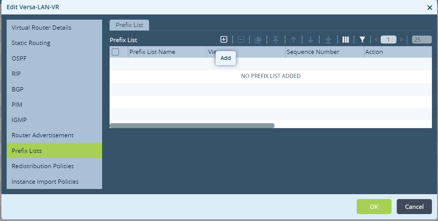
First we start with Local Data Centers configuration where Anycast DNS service hosted. In this task we will modify Device Template that has been created from the Workflow wizard. From Director UI navigate to
Configuration -> Templates -> Device Templates and open Anycast-DC template.
Picture 4
Under
Networking -> Virtual Routers, click on Versa-LAN-VR (Local Area Network organizations Virtual Router). Open Prefix Lists tab and create a new prefix list that will be located centrally in Local Data Centers configuration.
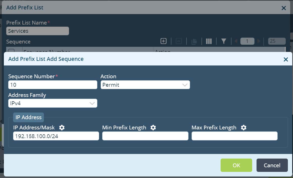
Picture 5
Set the name and permit Local Data Center Services subnets. In this example we match Anycast DNS subnet. Please note, the subnet ranges can be parameterized (gear icon) if required for other services. As a result the same configuration can be reused and scaled across multiple Local Data Centers with unique variables set for different services subnets. Click
OK.
Picture 6
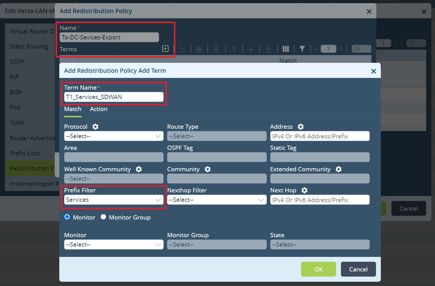
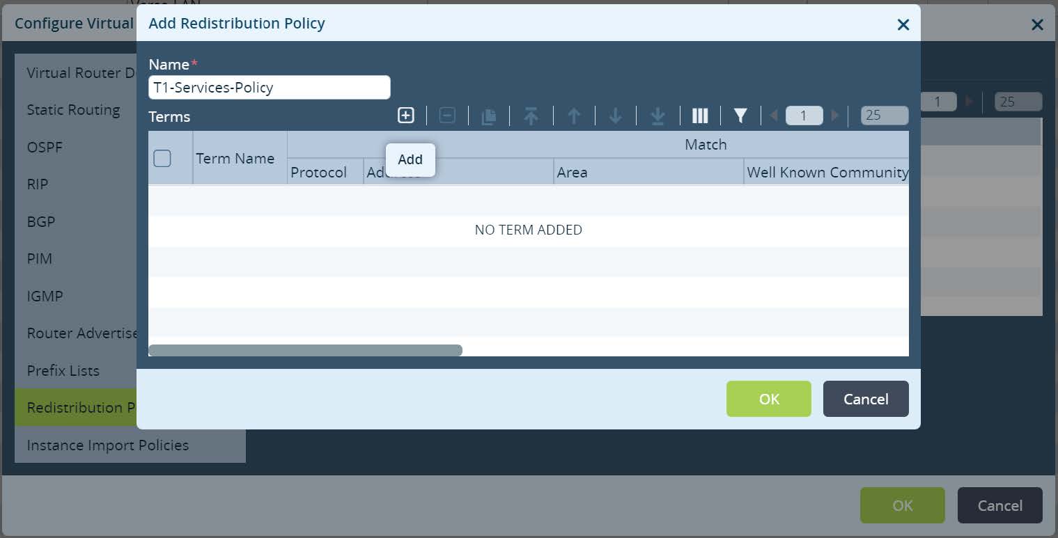
Navigate to
Redistribution Policies and create a new Policy. Set the Policy name and click + to create a new Term. Set the Term name and match Prefix Filter that has been created to identify Local Data Center Services subnets. Default action permit should be selected under the action tab.
Picture 7
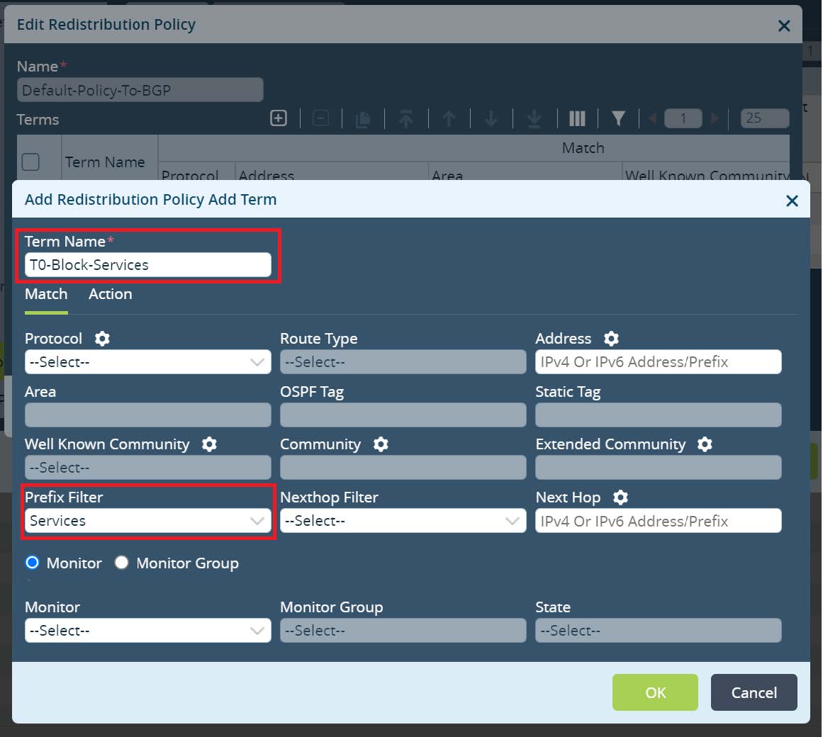
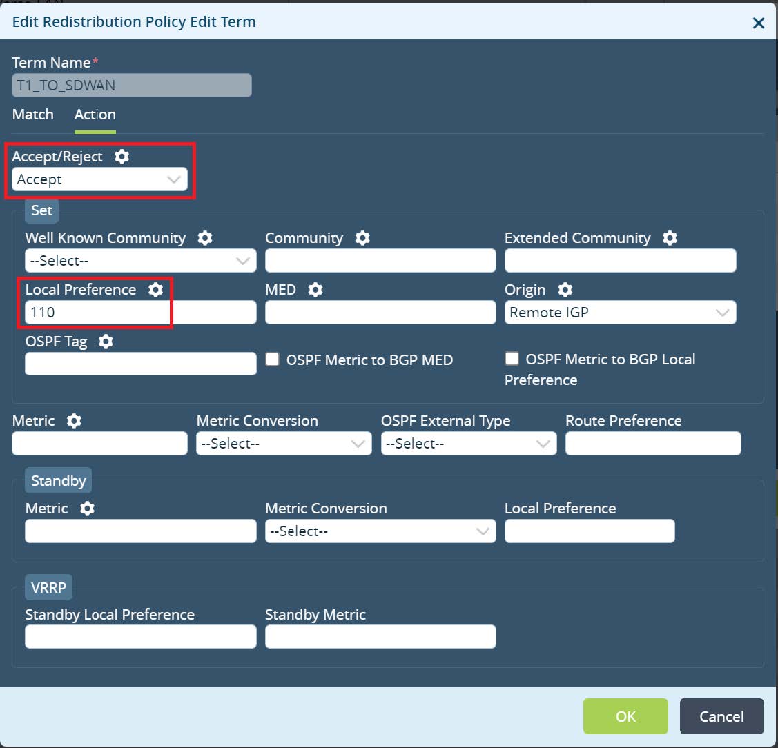
Click
OK until Versa-LAN-VR menu. Next open Default-Policy-To-BGP under redistribution policies and create a new Term there. Set the Term name and match Prefix Filter that has been created to identify Local Data Center Services subnets.
Picture 8
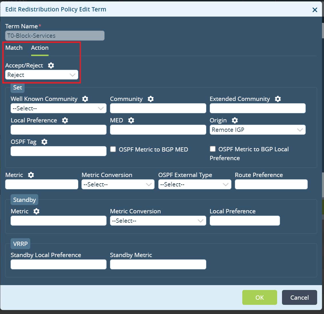
Under the Action tab set the action as reject and click
OK.
Picture 9
Move the newly created Term on top and click
OK to save all changes for the Versa-LAN-VR.
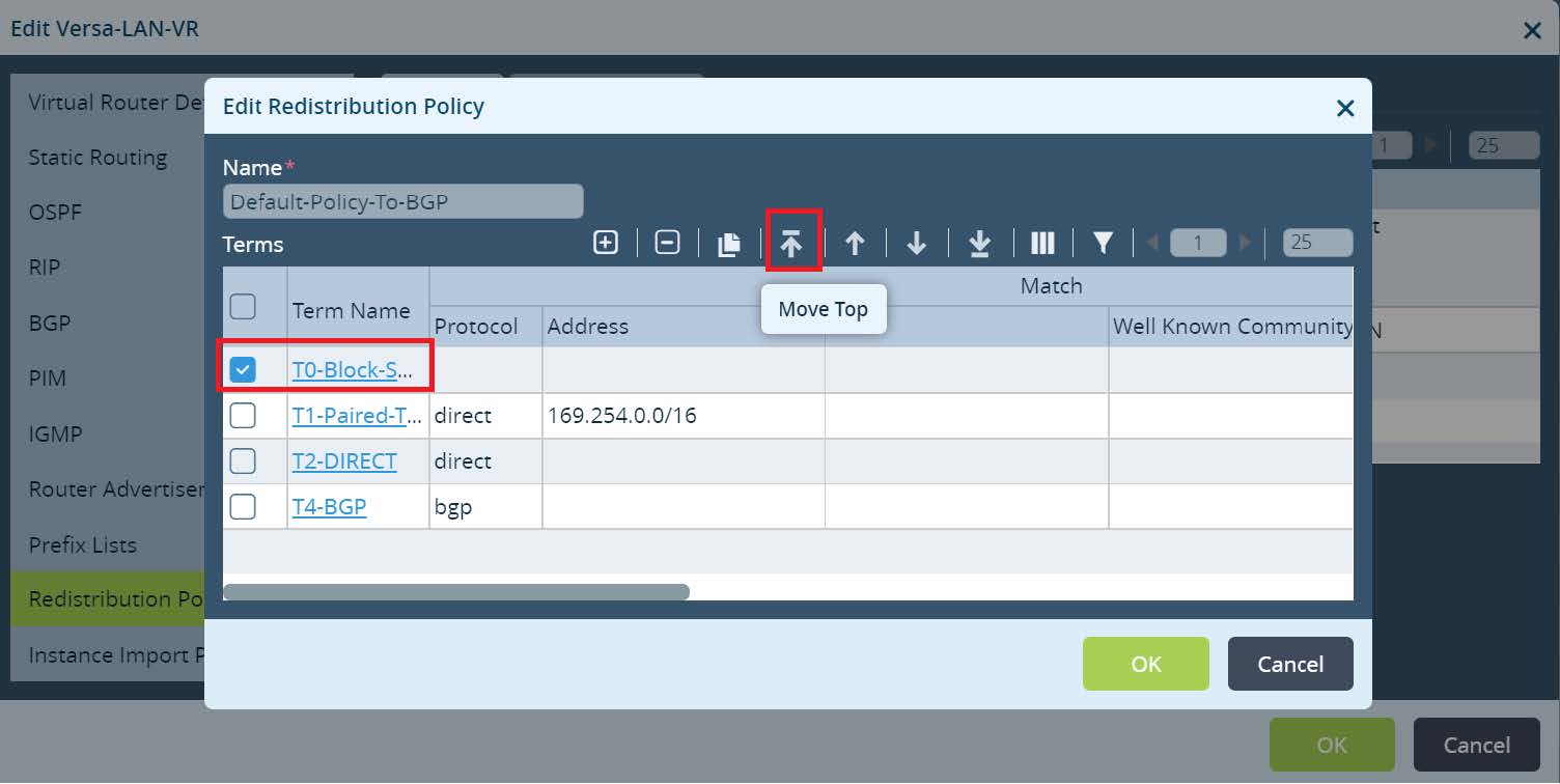
Picture 10
Under
Networking > Virtual Routers create a new DC-Services-Export virtual routing instance.
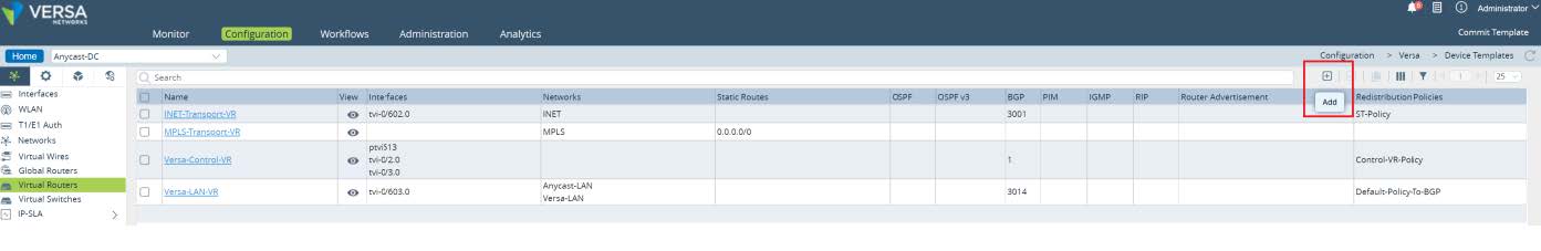
Picture 11
Under
Virtual Router Details configure instance name, set Instance type as Virtual routing forwarding instance, set custom Global VRF ID, parametarized Route Distinguisher value and assign VRF Export Target as shown at Picture 12.
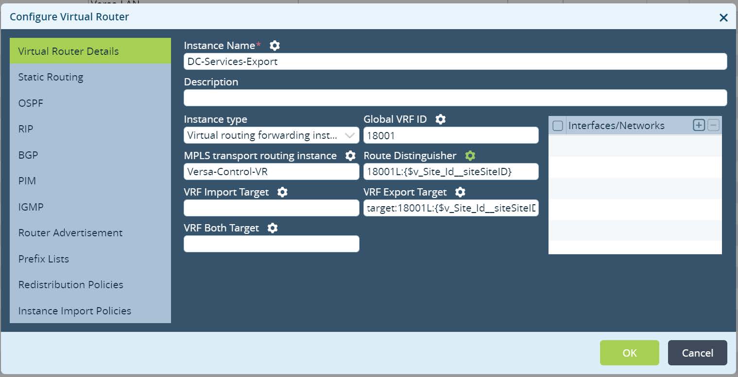
Picture 12
Next open Redistribution Policies and create a new policy.
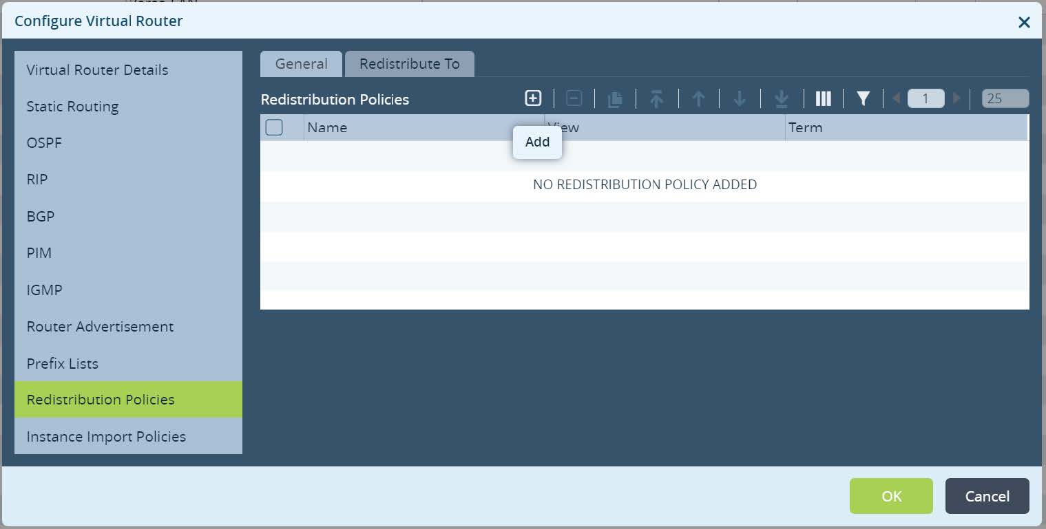
Picture 13
Set Redistribution Policy name and click + to create a new term.
Picture 14
Set a term name, action accept and assign Local Preference 110. Match criteria leave as default (match any).
Picture 15
Click
OK until Virtual router menu appear. Navigate to “Redistribute to” tab and create a new redistribution for IPv4 unicast, Destination BGP and newly created Policy Name.
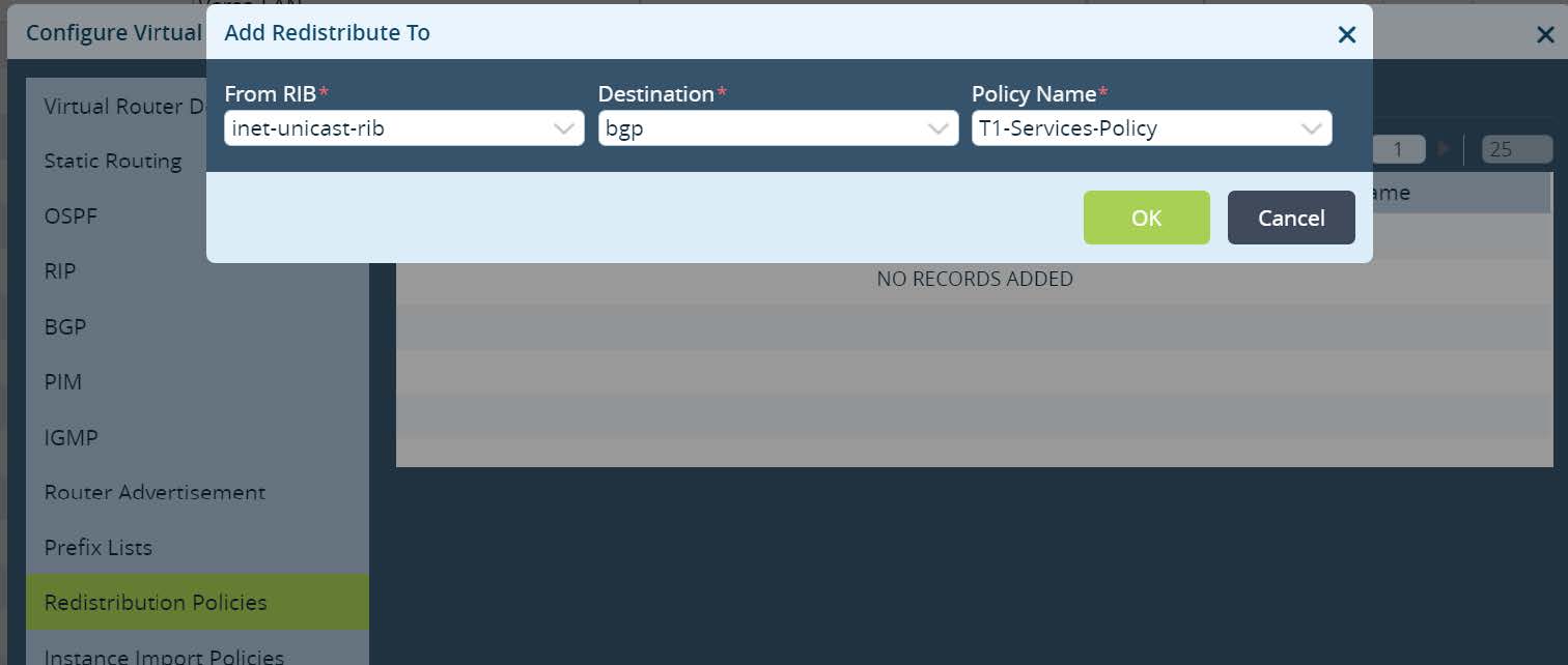
Picture 16
Click
OK and go to Instance Import Policies. Click + to create a new instance import policy. Select import from the Versa-LAN-VR IPv4 address family and previously created Policy Name inside Versa-LAN-VR.
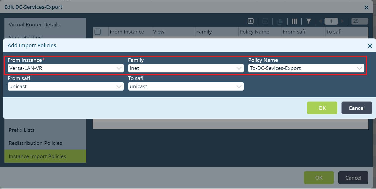
Picture 17
Lastly go to
Others -> Organization -> Limits and edit your organization limits to add newly created routing instance.
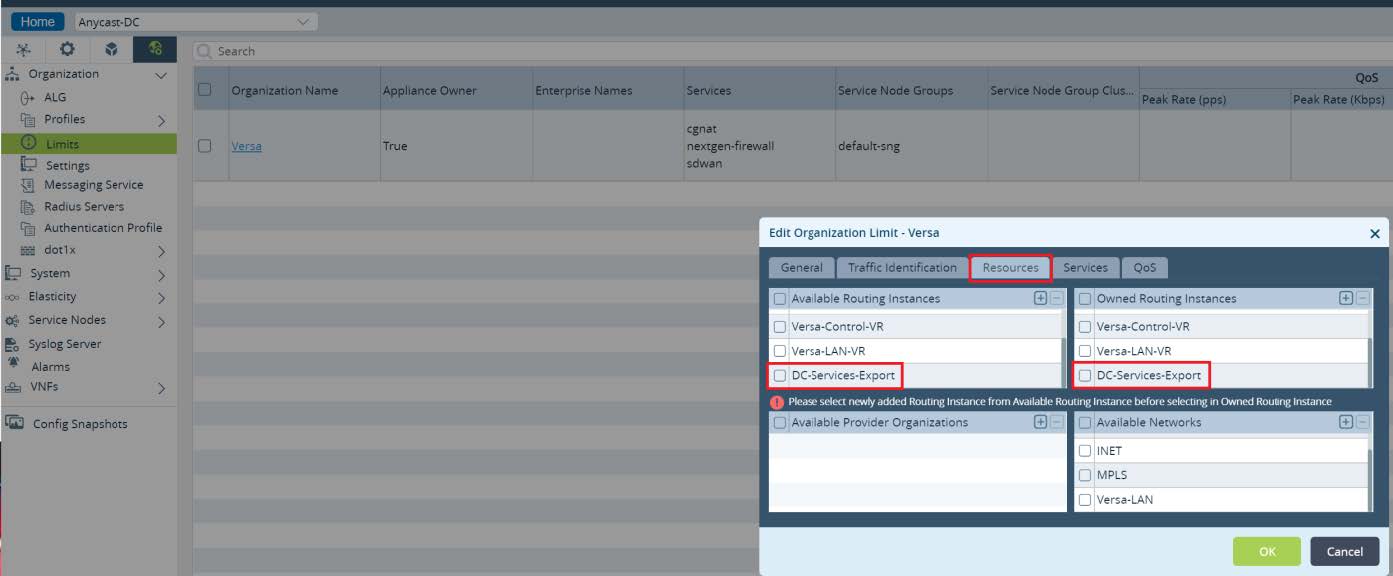
Picture 18
Finally commit the above changes to all Local Data Centers. As a result of this configuration, Local Data Centers Services subnets will be advertised with unique Extended Community to SDWAN network. Unique value for Extended Community will be set by Versa Director automatically from the second part of its value which is dependent on the site id
18001L:{$v_Site_Id__siteSiteID}.
In the second part of this design implementation we will leverage Service Templates. The goal of the Branch configuration is to import Anycast DNS service subnet from its own Regional Local Data Center.
To create a new service template navigate to
Configuration -> Templates -> Service Templates from the Director UI. Click + to add a new template. Set the template type as general, select your organization and provide a name.
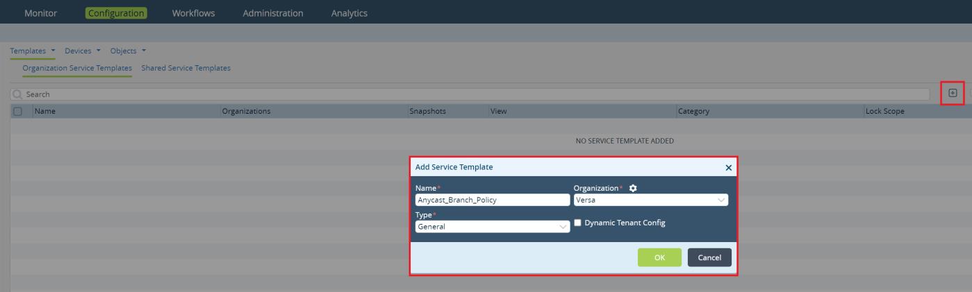
Picture 19
Click
OK to create a new Service Template. Open the template and go to
Networking > Virtual Routers. Click + to add a new virtual router.
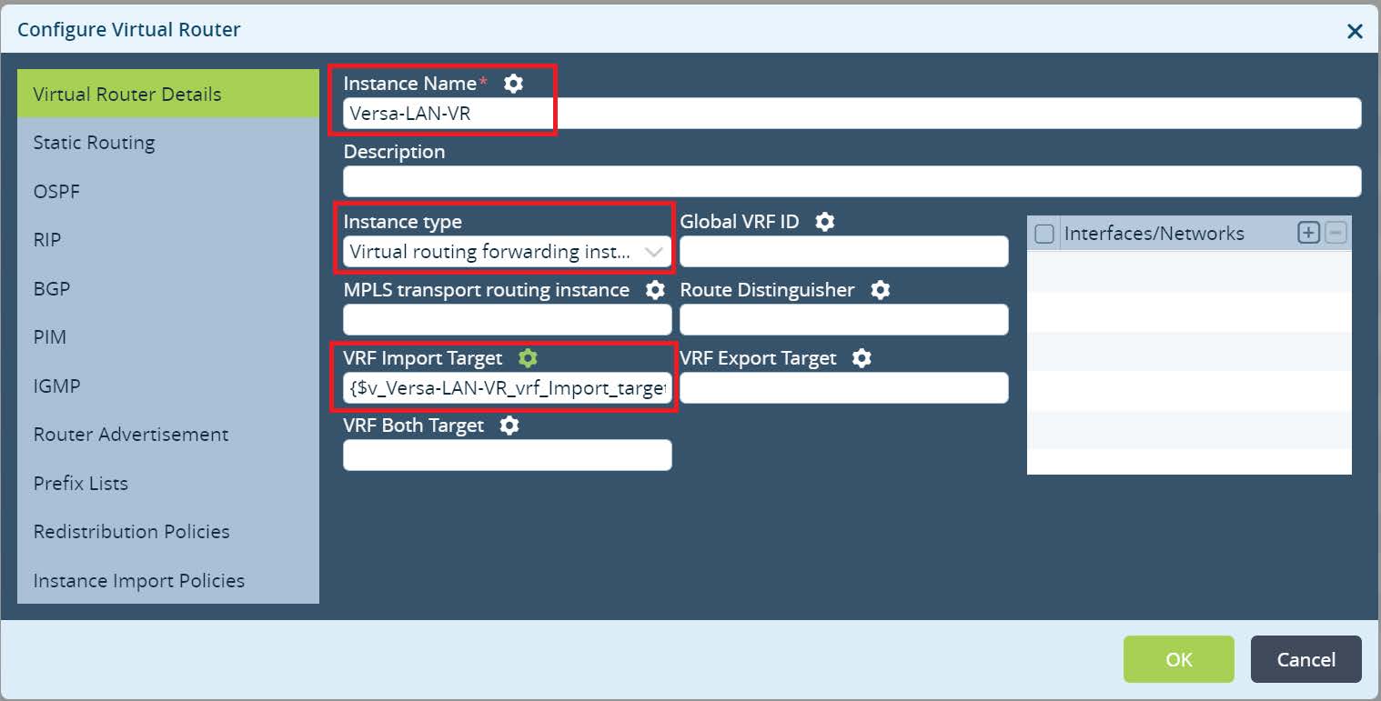
Picture 20
Set the Instance name. It should match to your LAN Virtual Router instance name used in Branches. Select Instance type as a Virtual routing forwarding instance. Click on the gear icon to parameterize VRF Import Target value. This will set a variable to VRF Import Target value that will be used in the device Bind Data. Parameterizing it will give a flexibility to reuse Anycast Service Template across Branches in different Regions. Click OK.
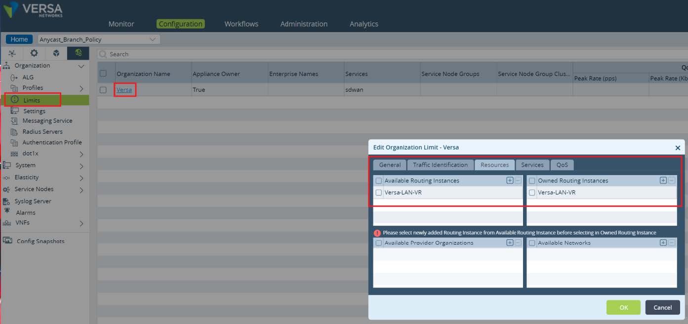
To allow usage of the created Virtual Router in a Service Template, we need to set organization-specific limits. Navigate to
Others -> Organization -> Limits and open your Organization by clicking on its name. In the pop up window open Resources and add new LAN-VR to Available and Owned routing instances. Click
OK. Service Template for Local Data Center Services is ready to use at ACME Branches.
Picture 21
To apply a new Service Template to our Branches navigate to
Configuration -> Devices -> Device Groups. In this setup ACME uses a single device group for Branches in all Regions. If your Organization uses multiple Device Groups repeat the steps below for all of them.
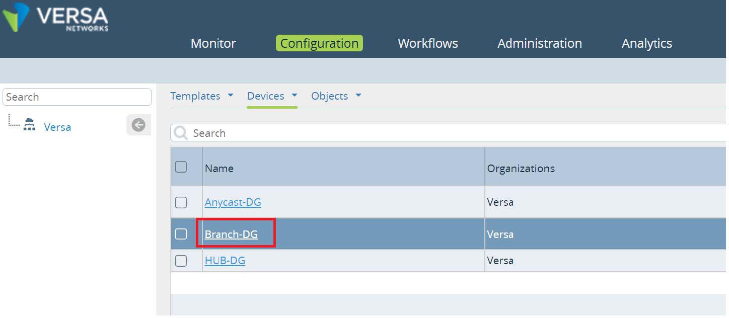
Picture 22
In the Device Group configuration click on
Device Service Templates Association button.
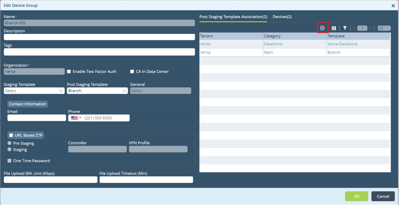
Picture 23
New window will pop up. Click on + to add a new service template association. Select your template and click
OK.
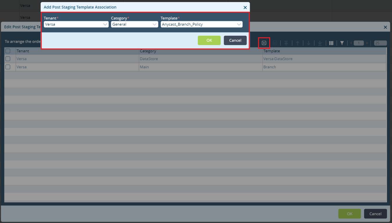
Picture 24
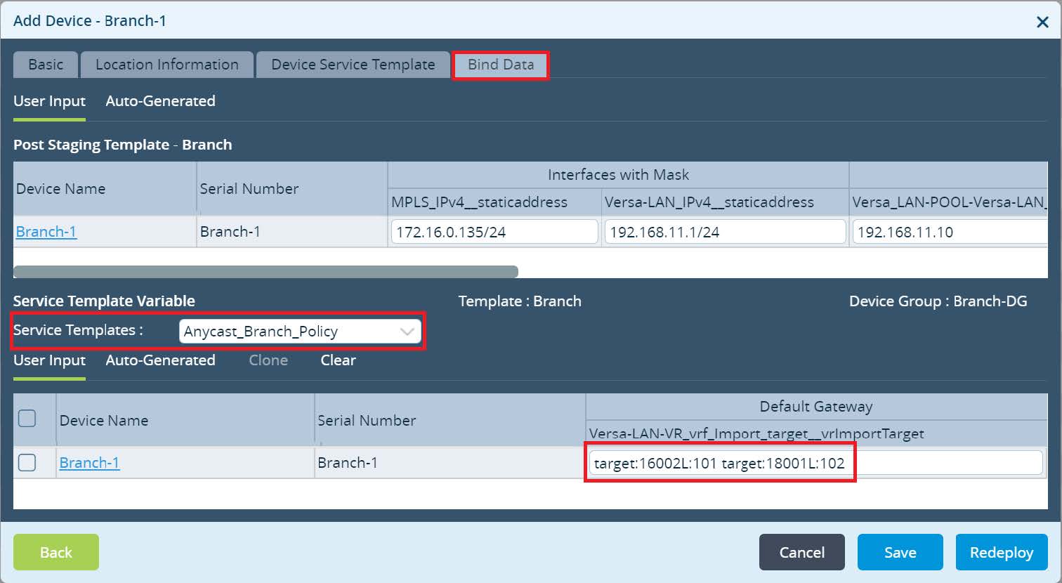
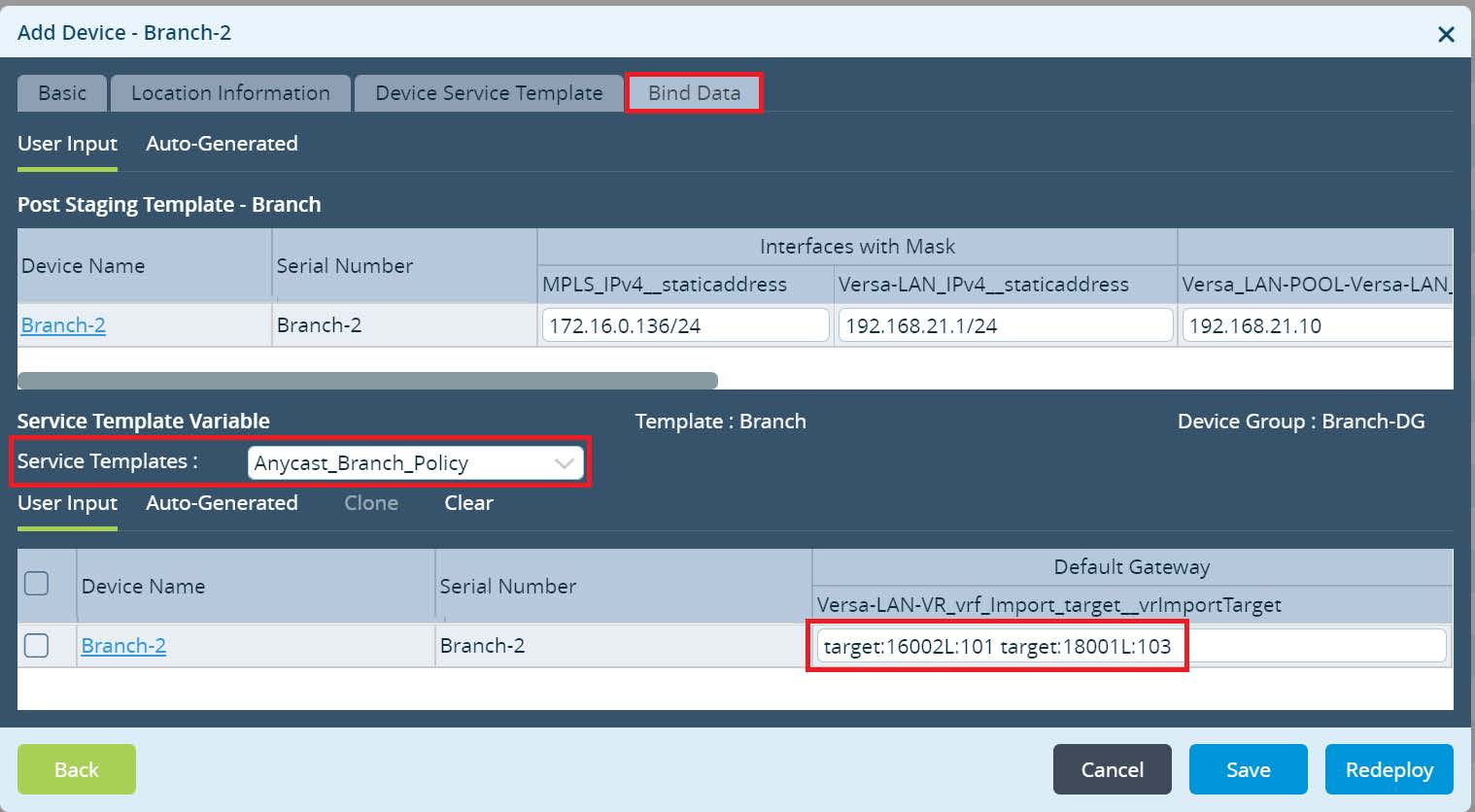
After adding the Service Template click OK to finish Device Group Configuration. Final step is to configure a Bind Data for the Branch devices and commit. Navigate to
Workflows -> Devices ->
Devices and add a Bind Data to your Branches.
For the Branch-1 use VRF Export Target assigned in the LAN-VR-Export from the Global Data Center HUB configuration as well as VRF Export Target assigned in the DC-Services-Export at the Local Data Center from Orange Region. For the Branch-2 use VRF Export Target assigned in the LAN-VR-Export from the the Global Data Center HUB as well as VRF Export Target assigned in the DC-Services-Export at the Local Data Center from Purple Region. Click
Redeploy to deploy your devices with a new LAN-VR import target values.
Picture 25
Picture 26
Commit the new changes to your devices.
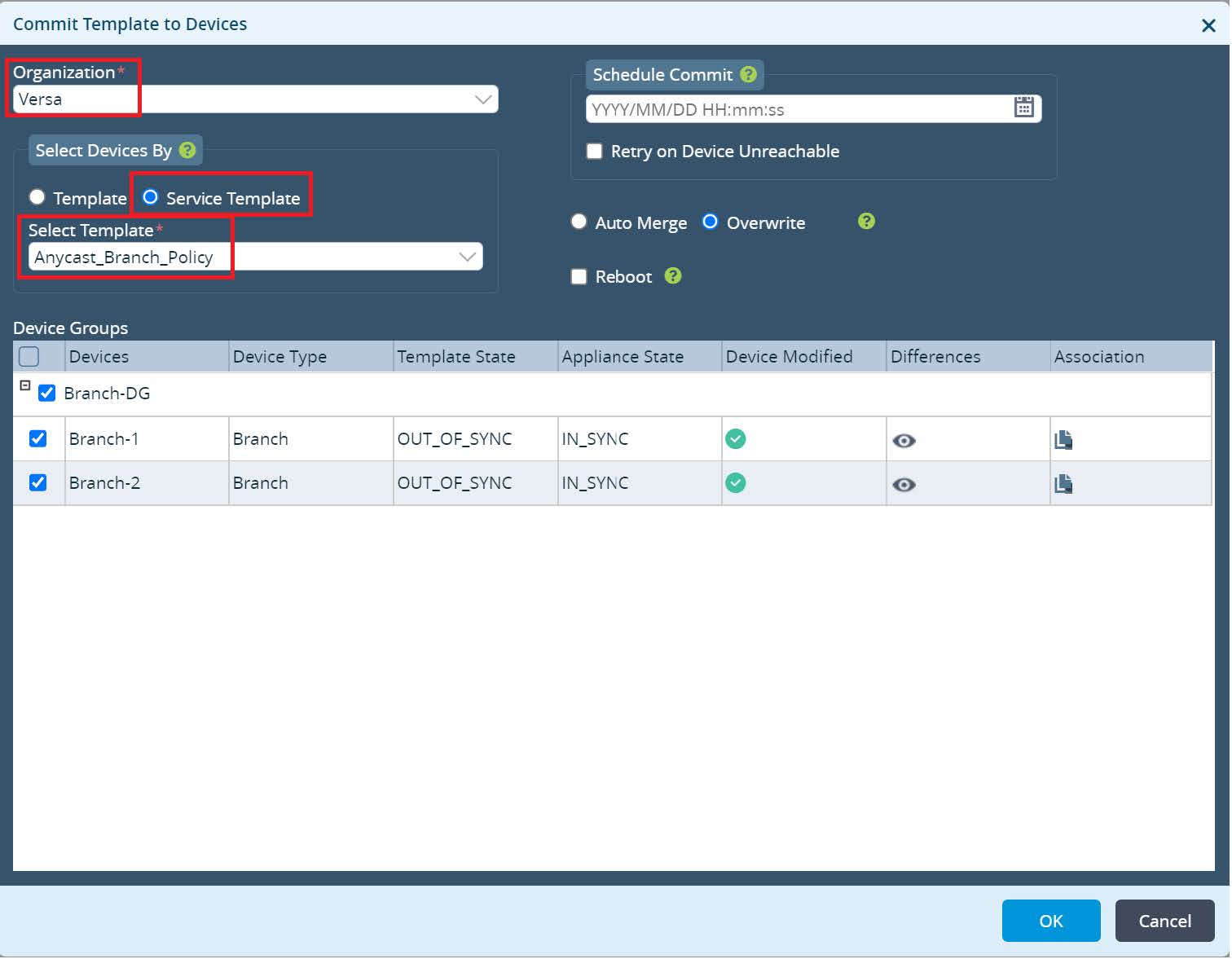
Picture 27
Lets verify. From Director UI navigate to the
Monitor -> Devices -> Branch-1. As per output below, Branch-1 has primary route via Anycast-DC1 and backup route via HUB-DC while route via Anycast- DC2 in Purple Region is not installed. Branch-2 has primary route via Anycast-DC2 and backup route via HUB-DC while route via Anycast-DC1 in Orange Region is not installed.
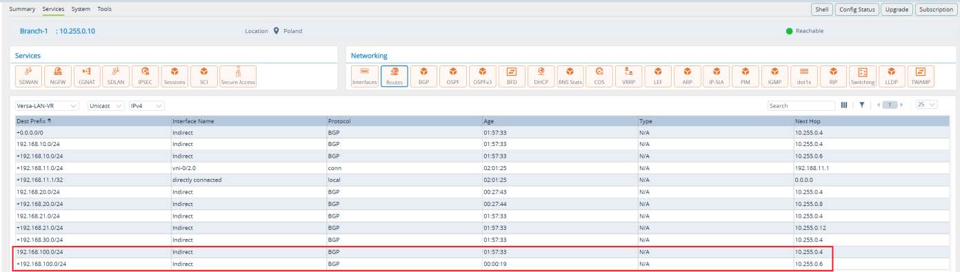
Picture 28
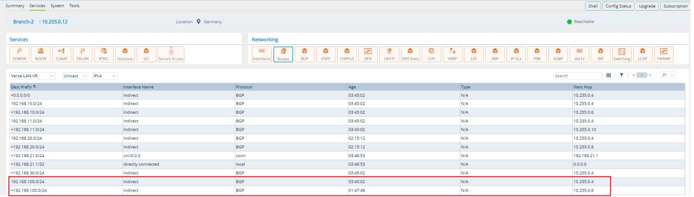
Picture 29
Conclusions
Based on the custom Anycast proximity requirement we learned how Versa Secure SDWAN solution provides technological flexibility using Single Pain of Glass orchestration platform. Network administrator can customize data plane flows and influence globally predefined topology based on the custom needs in an automated way. Additionally, we saw an example how to scale hierarchical configuration across hundreds or thousands of WAN Edge devices with using Service Templates.


