CCONFIGURING DISJOINT UNDERLAY CONNECTIONS ON VERSA CONTROLLER FOR EACH MPLS VPN CLIENT
Author: Fatih Isiktas
A. Introduction
This article describes the use case of creating separate underlay connections on Versa Controller to provide complete control plane segmentation to multiple MPLS VPN clients. From a service provider SD-WAN deployment perspective, the common approach is to provide a single VPN for all SD-WAN data planes and control planes, because the SD-WAN overlay provides granular separation for all customers. In this practice, the idea is to configure the SD-WAN Controller nodes with two transport virtual routers (which form the underlay) that have connections to an internet feed and a common VRF in the MPLS-VPN network. However, if a service provider has security regulations prohibiting VRF leaks in their infrastructure or if it does not want to deal with providing unique MPLS IP address scope to its customers, it can choose a design where disjoint underlay connections are created on the Versa Controller.
The multitenancy capability of the solution and the role of the Versa Controller will be briefly explained before the use-case configuration details are discussed.
B. Multi-tenancy
Multitenancy refers to an architecture where a single instance of software runs on a server and serves multiple tenants. Multitenancy allows service providers to optimize the utilization of the networking assets. Versa solution supports multi-tenancy at all levels of the solution. A tenant in Versa Director refers to an organization that shares common access with specific privileges to the software instance. The Versa Operating System multitenancy can be defined as complete control plane and data plane isolation among various tenants. As illustrated in Figure-1, same or disjoint underlay transports can be used to form a multi-tenant SD-WAN fabric.
C. The Versa Controller
The Versa SD-WAN Controller, a specially configured VOS instance, deploys SD-WAN nodes. Versa Director communicates with each VOS instance through encrypted tunnels terminated at the Versa Controller. The Versa Controller creates IPsec tunnels that carry control-plane information to branches and hubs using either MPLS or internet transport networks, as shown in Figure 1.
Versa Networks SD-WAN architecture relies on secure IPsec-over-VXLAN overlay tunnels to transmit control-plane and data-plane traffic. Using overlay technologies provides traffic segregation, isolation, and privacy. In most cases, using separate overlay tunnels is sufficient for customer isolation, however, if a complete segmentation is required, underlay connections of SD-WAN components can also be isolated from each other.
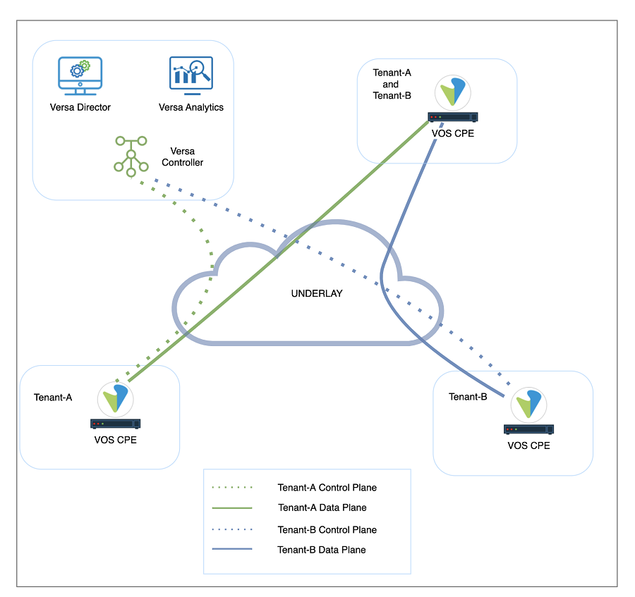
Figure 1: Versa Solution Architecture and Multi-tenancy
D. Use Case: Underlay Segmentation on Versa Controller
In a multi-tenant MPLS environment, service providers may want to extend the customer MPLS VPNs to the Versa Controllers to form the tenant control plane channels over separate underlay VPNs as shown in Figure 3. In this design, each control plane channel is created over a different MPLS VPN. This method has two main advantages over using a single MPLS connection on Versa Controller for multiple customer VPNs. Firstly, it provides more security to the customers since it does not cause any VRF leaks on the service provider’s MPLS infrastructure. Secondly, service providers do not need to provide a unique IP address block for each customer VRF, that is, the same IP address scope can be used for multiple customers. This can be achieved by creating different VRFs on the Controller underlay connection for each customer VPN. In other words, on Versa Controller, multiple wan networks can be created for multiple customers under the same transport domain for a complete control plane segmentation.
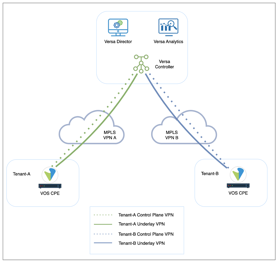
Figure 2: Disjoint underlay and overlay tunnels
Maximum 8 wan networks can be defined on Versa Controller through Versa Director Workflow windows in VOS versions 21.x. This limit will be increased to 15 in the new VOS version (version no: 22.1, eta Q4-2022). Since most service providers may have more than 8 customers, the configuration must be done through Versa Controller’s ‘appliance context’ windows which allow the creation of 1024 wan networks on Versa Controller.
E. Configuration Steps
There are four main steps to configure a new underlay connection on the Controller. The configuration steps are explained in detail in this section.
The summary of the configuration steps is listed below:
Step 1: Creation of tenants on Versa Director
-
- Adding a new Organization
Step 2: Addition of network objects to the Versa Controller for each tenant’s underlay connection
-
- Adding a new MPLS interface to the Controller
- Adding a new Network object to the Controller
- Adding the Network object to the Organization limits
- Adding a new WAN Network object to the Organization
- Adding a new MPLS VR to the Controller
- Adding routing information to the MPLS VR
- Adding the MPLS VR to the Organization limits
Step 3: SD-WAN and path configuration of each tenant on Versa Controller
-
- Adding a new WAN interface to the Controller’s ‘Site Config’
- Adding a new ‘path policy’ to the Controller
- Adding a new WAN interface to the Controller’s ‘Site’
Step 4: IPsec configuration of each tenant on Versa Controller
-
- Adding a new staging IPsec profile for the new MPLS network
- Adding a new IP address pool to the IPsec profile
- Synchronizing Controller’s config with Director
1. Creation of tenants on Versa Director
-
- A new organization/tenant is created by using the Versa Director ‘Workflow’ windows (Workflow>Infrastructure>Organizations). Figure 4 shows the fields where necessary information about the organization is collected. When the new organization is deployed, the tenant-related configuration is pushed to the Controllers automatically. We create a tenant ‘NEW-TENANT’ in our example.
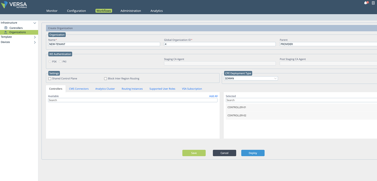
Figure 3: Workflow: Organization creation
2. Addition of network objects to the Versa Controller for each tenant’s underlay connection
- After a new tenant is created on the Director, a new interface and a virtual router are defined on the Controller for the new tenant. In our example, as shown in the screenshots below, a sub-interface is created under the existing MPLS port and an IP address is given to the sub-interface. This sub-interface is connected to the tenant’s VRF on the service provider MPLS network so that the customer’s edge devices can connect to the Controller through this network. We give 172.16.16.2/30 IP address to the sub-interface. The VLAN id is 606.
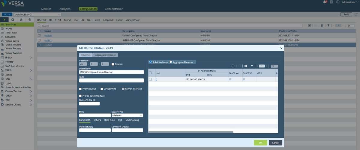
Figure 4: Controller interface configuration window
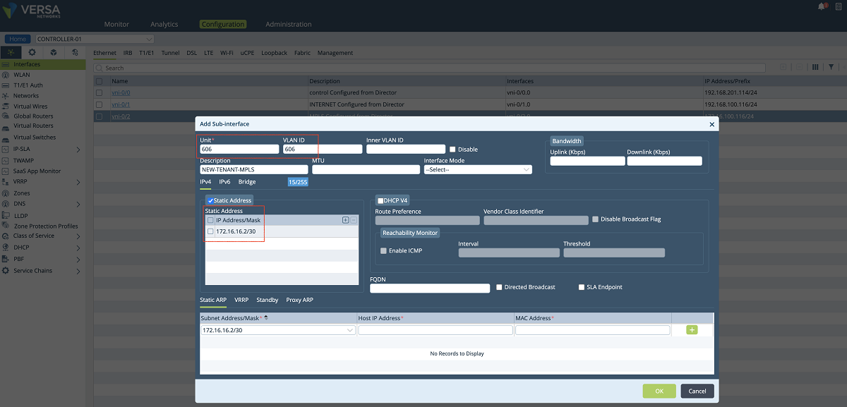
Figure 5: Controller IP address configuration window
- In the next step, a new network object is created and the sub-interface which is created in the previous step is attached to the network object. In our example, we create a network object named ‘NEW-TENANT-MPLS-NETWORK’, and we bind the interface ‘vni-0/2.606’ to it.
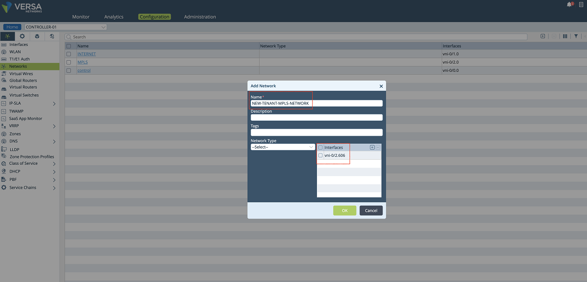
Figure 6: Controller network object window
- The new network object is added to the Organization limits under the Controller’s Configuration/Others/Organization/Limits hierarchy as shown in the figure below.
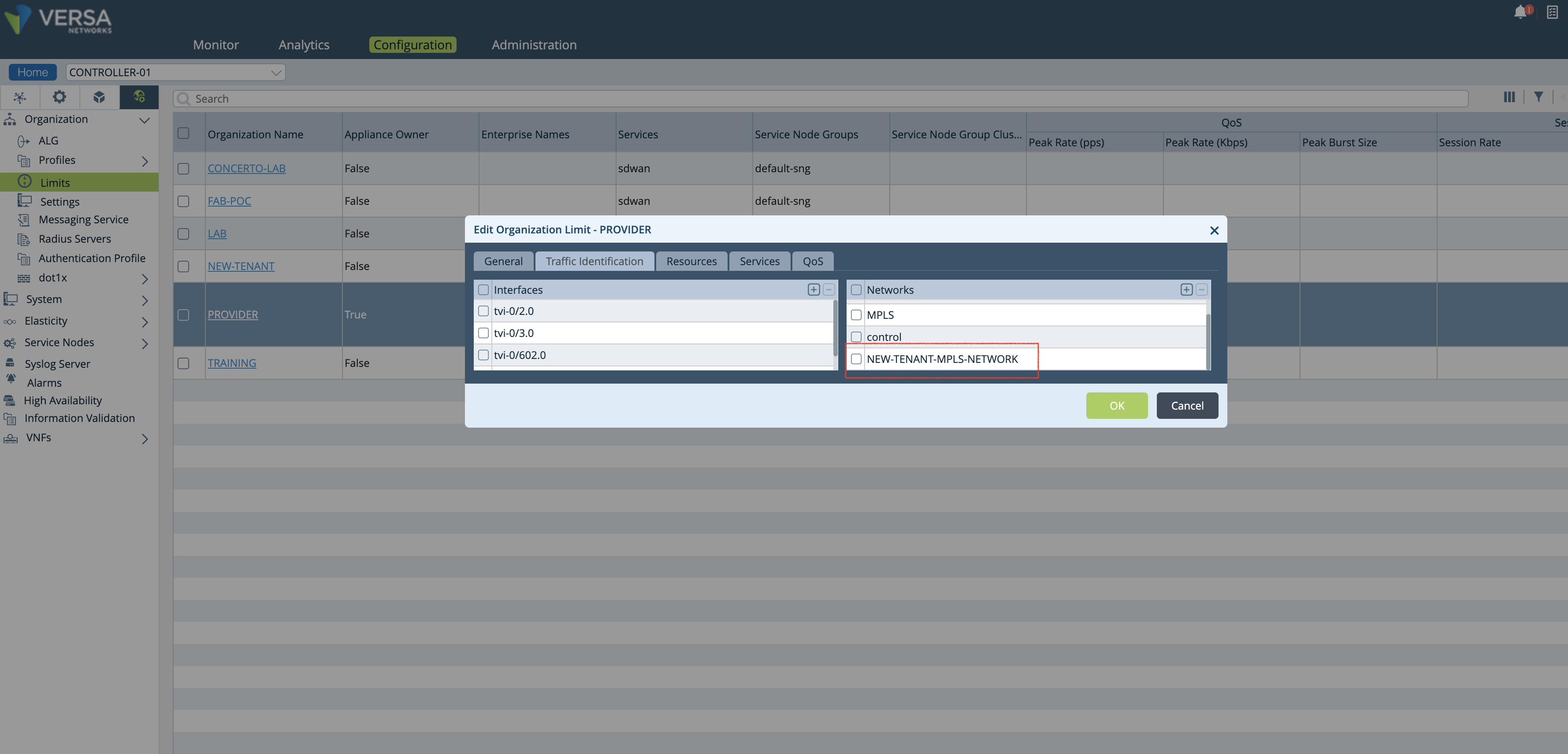
Figure 7: Controller org limit window
- A new WAN network is added to the organization’s ‘Wan network’ objects as shown in the Figure below.
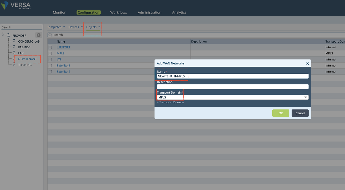
Figure 8: Add a new wan network to the org
- A new transport VR is created for each client to allow them to use the same IP subnets. To add a new VR, we click the ‘BUILD’ button as shown below. We give a name to the VR and attach the network object that we created in the previous step. In this example, ‘NEW-TENANT-MPLS-VR’ is the name of the VR.
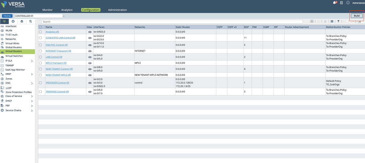
Figure 9: Controller VR list
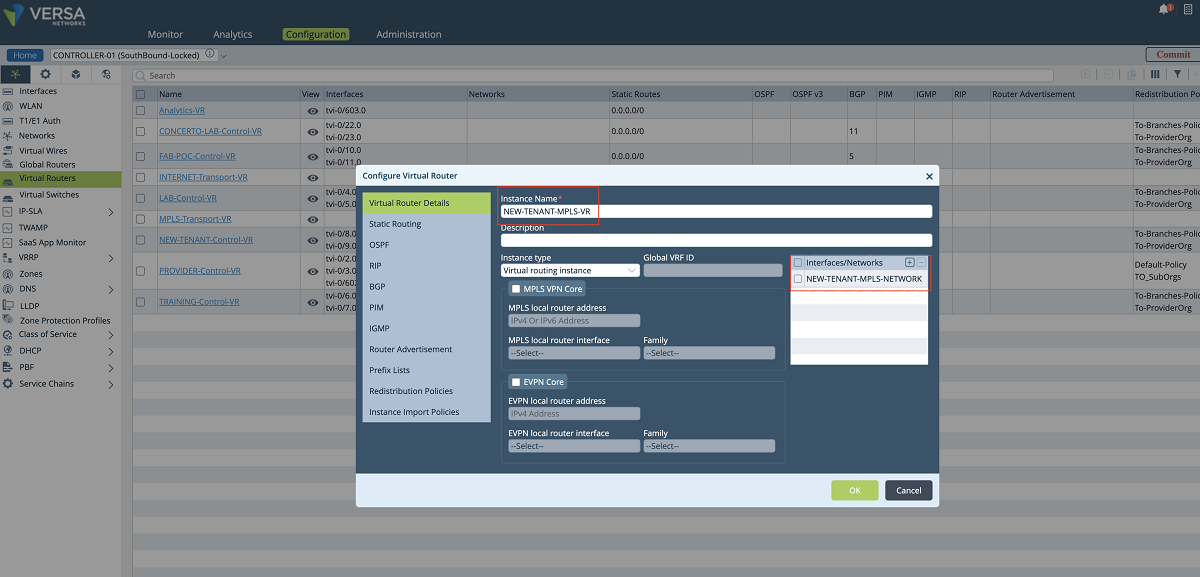
Figure 10: VR and network association window
- Since the new VR will send the underlay traffic to the MPLS network, a default route must be given to the VR or a dynamic routing protocol must be enabled for peering with the MPLS router. The figures given below show the static route method (default route). In our example, the default gateway is 172.16.16.1.
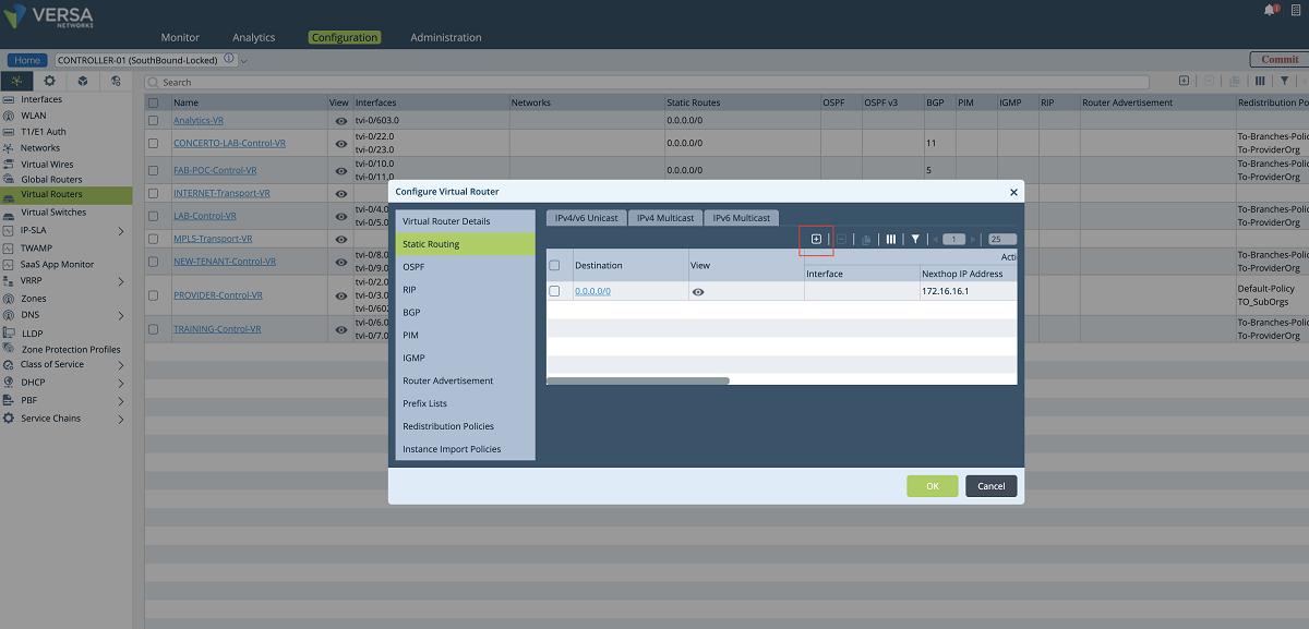
Figure 11: Adding a route to the new underlay VR
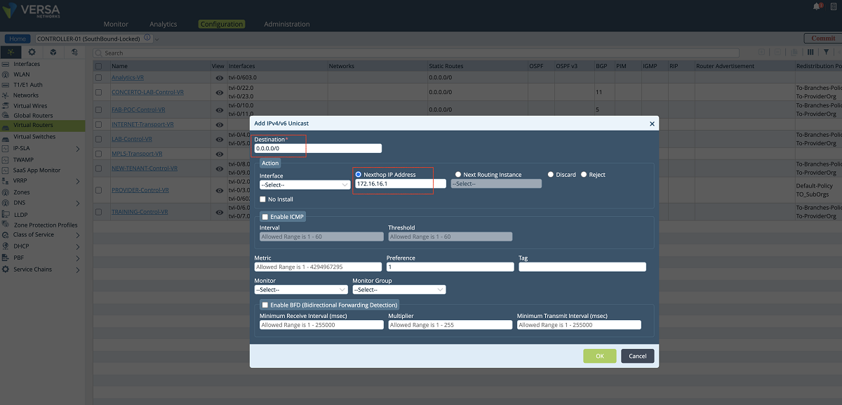
Figure 12: Adding a route to the new underlay VR – 2
- The last step for creating the VR on the Controller is to add the VR to the ‘Provider’ limits. We go to the Controller’s Configuration/Others/Organization/Limits hierarchy as shown in the figure below. In this window, the new VR is added to the ‘Available Routing Instances’ and ‘Owned Routing Instances’ panes. Then the VR configuration is sent to the Controller by clicking the ‘Commit’ button.
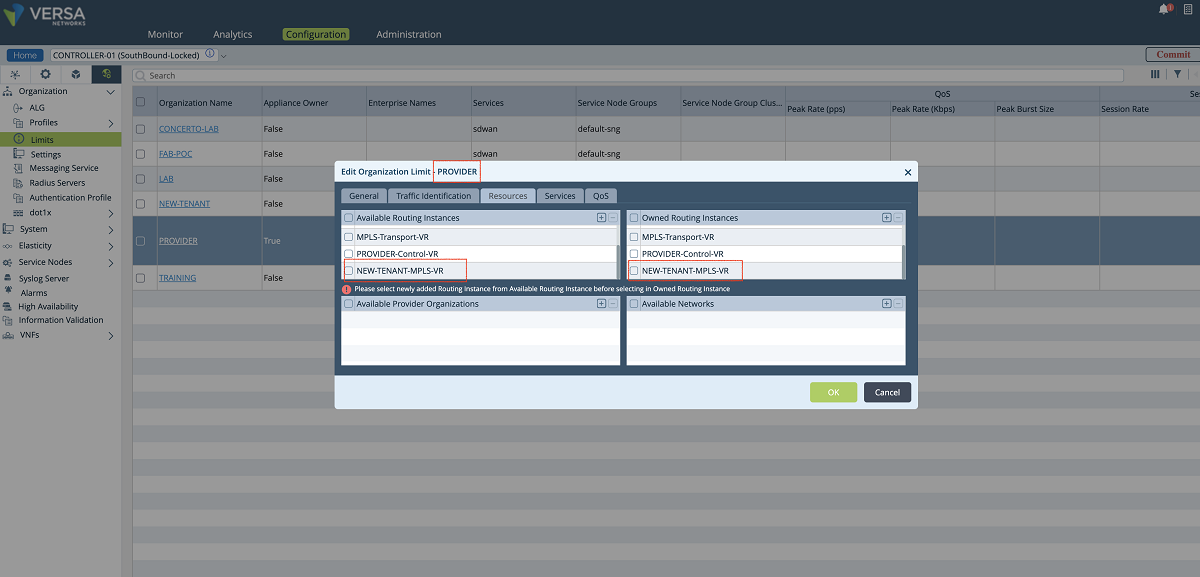
Figure 13: Organization limit configuration
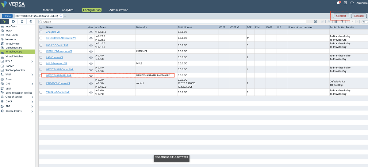
Figure 14: Controller VR list -2
3. SD-WAN and path configuration of each tenant on Versa Controller
- In the third step, SD-WAN and path configuration for each tenant is performed under the Controller’s Configuration/Services/SD-WAN section. As shown in the figures below, a new WAN interface is defined under the ‘Site Config’ window. The ‘Provider’ organization must be selected in the ‘Organization’ drop-down menu. The new interface is selected and added to the MPLS transport domain with a new circuit name. In our example, we add the vni-0/2.606 interface to the MPLS domain with the ‘NEW-TENANT-MPLS’ name.
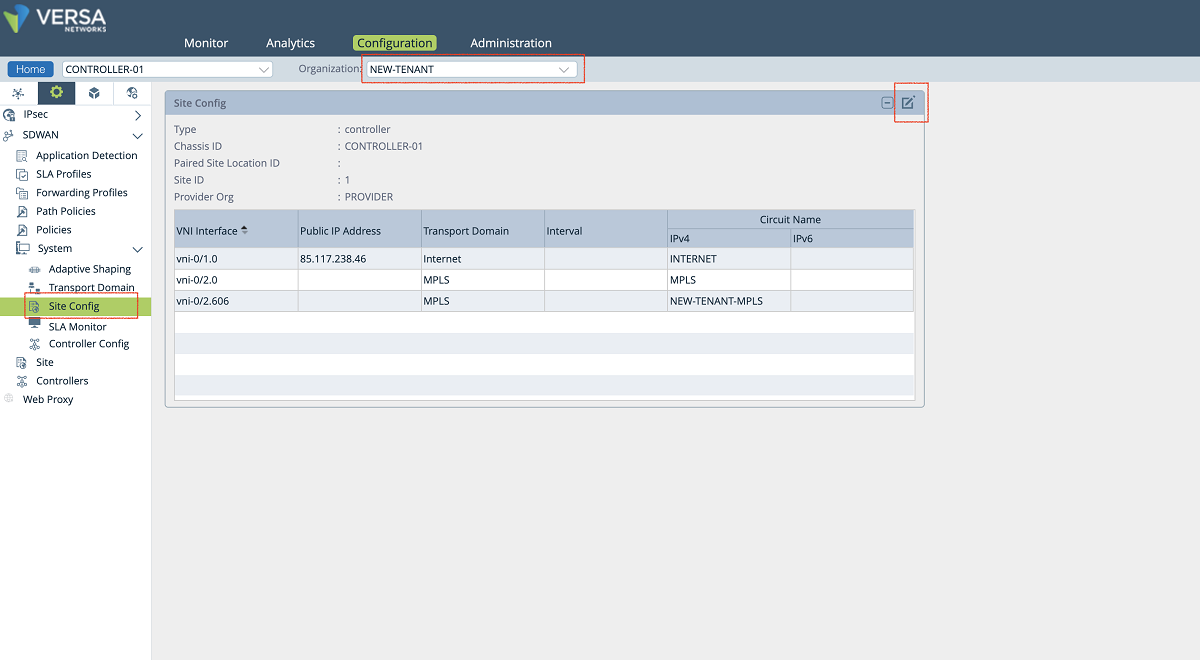
Figure 15: Controller site-config window
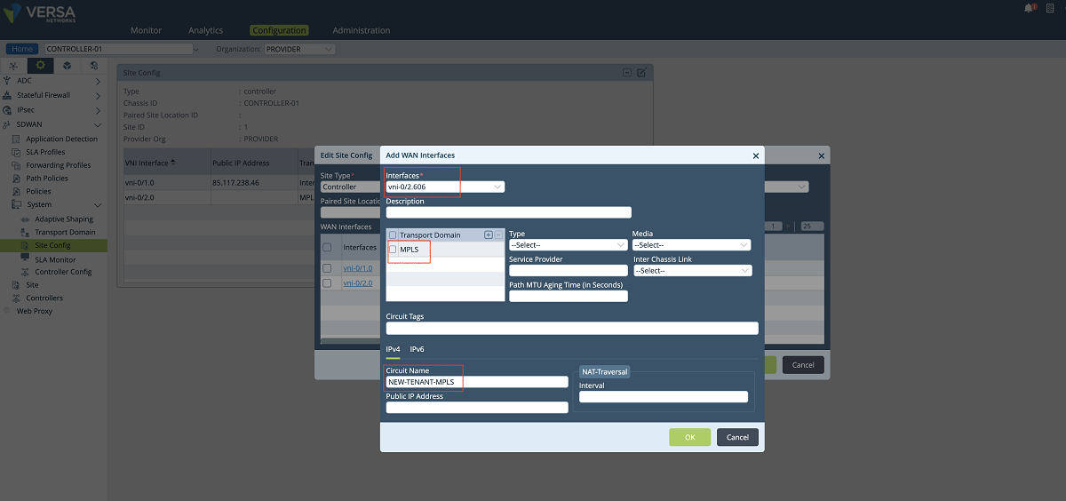
Figure 16: Controller Wan interface config
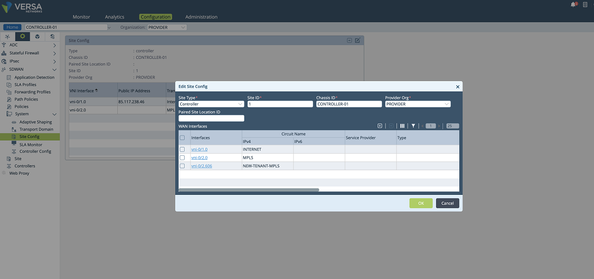
Figure 17: Controller Wan interface config – 2
- A new SLAM policy is created and associated with the new tenant under the ‘Path Policies’ configuration window. The ‘NEW-TENANT’ organization must be selected in the ‘Organization’ drop-down menu. In our example, the name of the path policy is ‘SLAM_Policy_vni-0/2.606’.
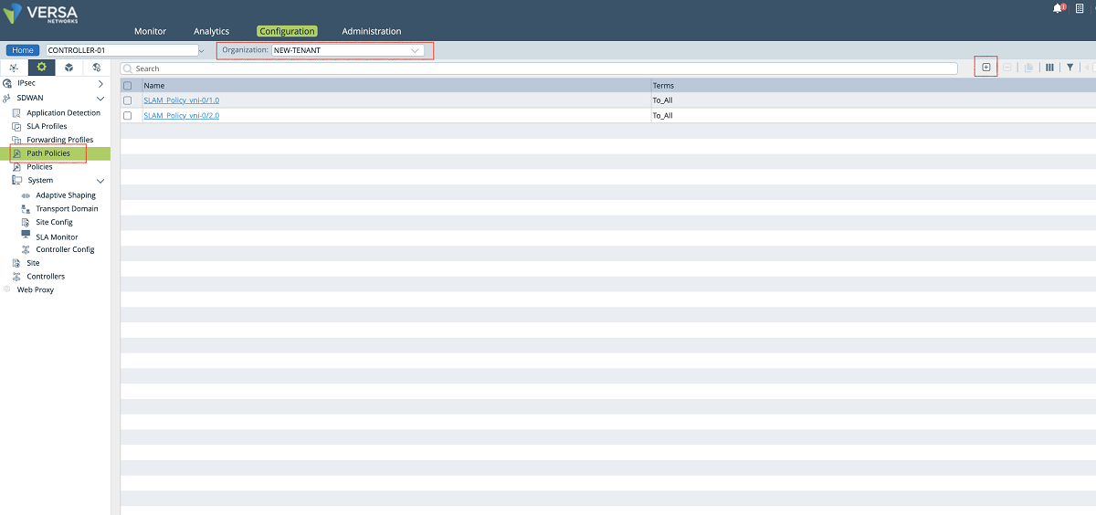
Figure 18: Controller path policy configuration
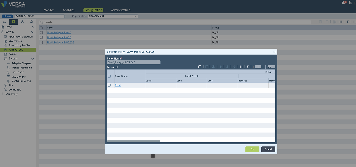
Figure 19: Controller path policy configuration – 2
- The last configuration in the SD-WAN section is to add a new WAN interface to the Controller’s ‘Site’ config. We create a new WAN interface by selecting the tenant’s sub-interface and its SLAM policy as shown below. In this setup, we add the vni-0/2.606 interface along with the SLAM_POLICY_vni-0/2.606 policy. After adding this new MPLS interface for the tenant, the old MPLS interface can be removed from the list since it won’t be used for the control plane anymore. The ‘NEW-TENANT’ organization must be selected in the ‘Organization’ drop-down menu.
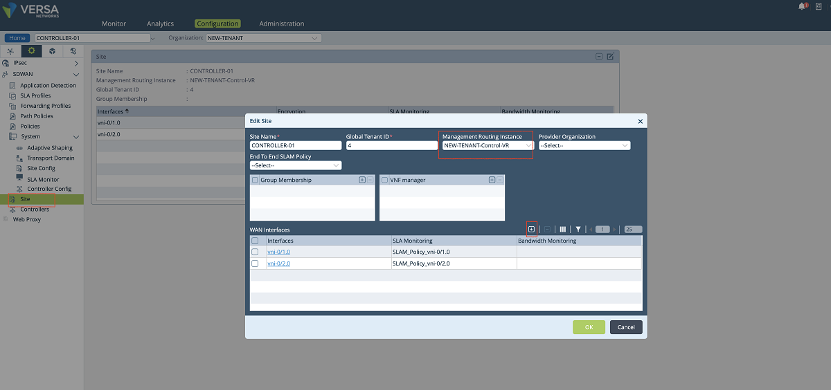
Figure 20: Controller site config window
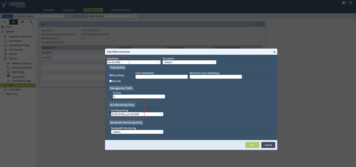
Figure 21: Controller site config window – 2
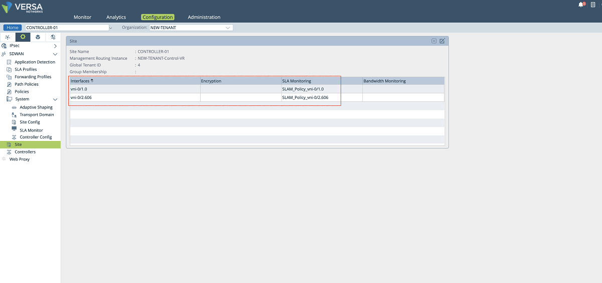
Figure 22: Controller site config window – 3
4. IPsec configuration of each tenant on Versa Controller
- The last step is to define the staging IPsec profile in case the customer CPEs need to be onboarded through the new MPLS interface. To create a new IPsec profile we use Controller’s Configuration/Services/IPsec/VPN Profiles window. As shown in the figures below, the MPLS-Controller-StagingIpsec profile can be cloned to create a new profile. In the ‘VPN Profile’ window, a name is given to the profile, and the new VR and the new interface are selected in the proper fields. In our example, we selected ‘NEW-TENANT-MPLS-VR’ as selected under the routing instance (If the new VR is not listed in the drop-down menu refresh the page). Then local interface ‘vni-0/2.606’ is selected as the local interface. Other parameters can also be changed based on customer requirements.
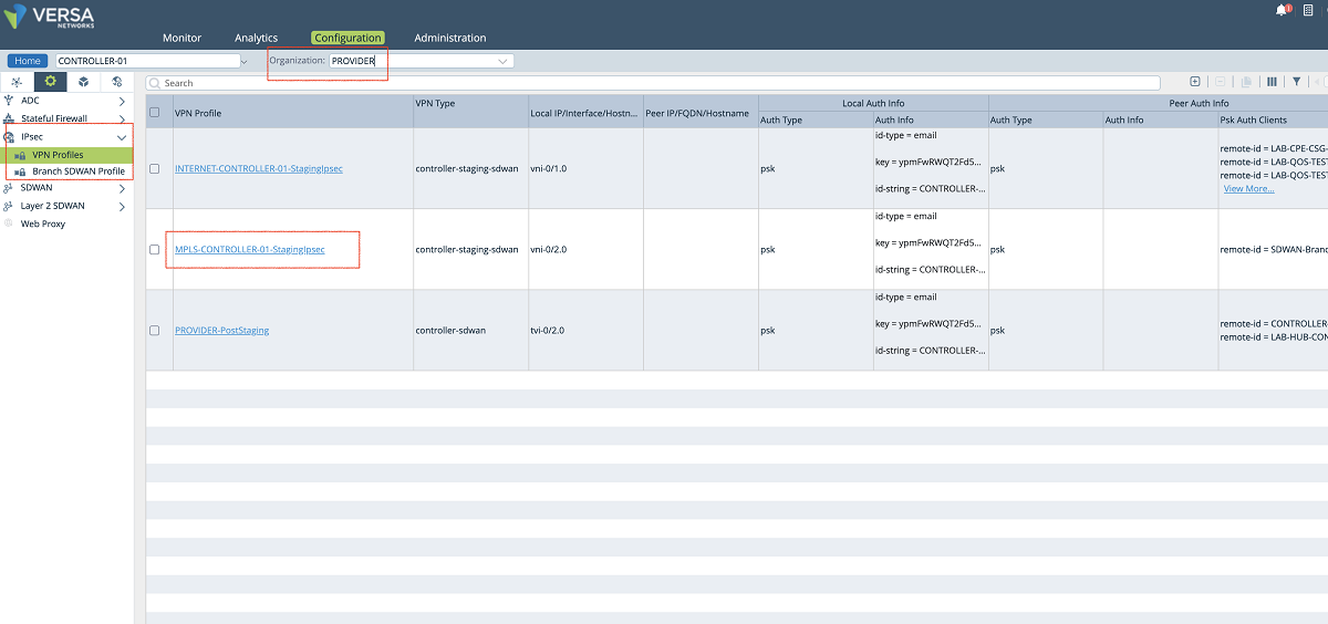
Figure 23: Controller IPsec configuration
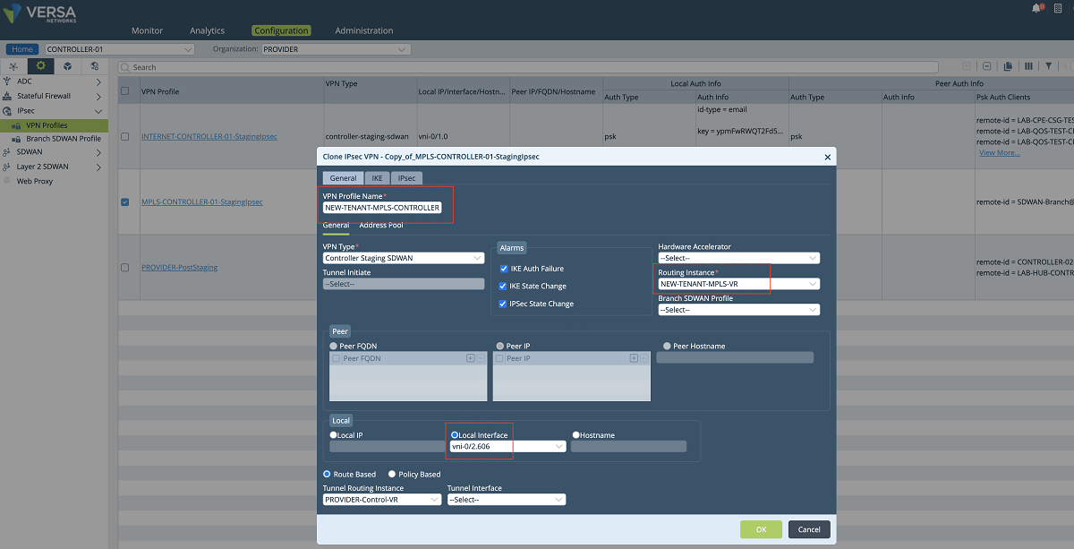
Figure 24: Controller IPsec configuration window
- The ‘Address Pool’ can also be changed in the new VPN profile to separate the pool from other client VPN pools. The IP pool is used to assign IP addresses to the CPEs during the CPE onboarding. The pool should not overlap with the SD-WAN overlay pool. Since the GUI does not allow to make changes, the configuration needs to be added to the Controller’s command line. The commands given below should be issued in the config mode on the Controller. Then the configuration must be synchronized with Director as shown in the Figure below. In our example, we assign 172.20.2.0/26 subnet as the VPN pool. We also add the Director’s southbound IP addresses to the accessible subnets. A static route must be added to the Director to provide reachability between the Director and the CPEs during the staging.
Commands to add new staging pool to Controller
admin@CONTROLLER-01: ~] $ vsh allow-cli (hit enter, give admin password)
admin@CONTROLLER-01: ~] $ cli (hit enter)
admin@CONTROLLER-01-cli> configure (hit enter)
admin@CONTROLLER-01-cli(config) %
admin@CONTROLLER-01-cli(config)% delete orgs org-services PROVIDER ipsec vpn-profile NEW-TENANT-MPLS-CONTROLLER-01-StagingIpsec address-pools address-range <cloned address pool>
admin@CONTROLLER-01-cli(config)% set orgs org-services PROVIDER ipsec vpn-profile NEW-TENANT-MPLS-CONTROLLER-01-StagingIpsec address-pools address-range 172.20.2.0-172.20.2.63 netmask 255.255.255.192 accessible-subnets <Primary Director Southbound IP>/32
admin@CONTROLLER-01-cli(config)% set orgs org-services PROVIDER ipsec vpn-profile NEW-TENANT-MPLS-CONTROLLER-01-StagingIpsec address-pools address-range 172.20.2.0-172.20.2.63 netmask 255.255.255.192 accessible-subnets <Secondary Director Southbound IP>/32
admin@CONTROLLER-01-cli(config)% set orgs org-services PROVIDER ipsec vpn-profile NEW-TENANT-MPLS-CONTROLLER-01-StagingIpsec address-pools address-range 172.20.2.0-172.20.2.63 netmask 255.255.255.192 accessible-subnets 172.20.2.0/26
admin@CONTROLLER-01-cli(config)% set routing-instances PROVIDER-Control-VR protocols bgp 1 prefix-list StagingPrefixes seq 3 address-family ipv4 unicast address-mask 172.20.2.0/26
admin@CONTROLLER-01-cli(config) % commit and-quit (hit enter)
c. After the configuration is added to the Controller in the command line, the configuration of the Controller needs to be synchronized with the Director. As shown in Figure 25, the Controller is selected, and the ‘Sync Config from Appliance’ button is used to pull the Controller’s configuration to the Director.
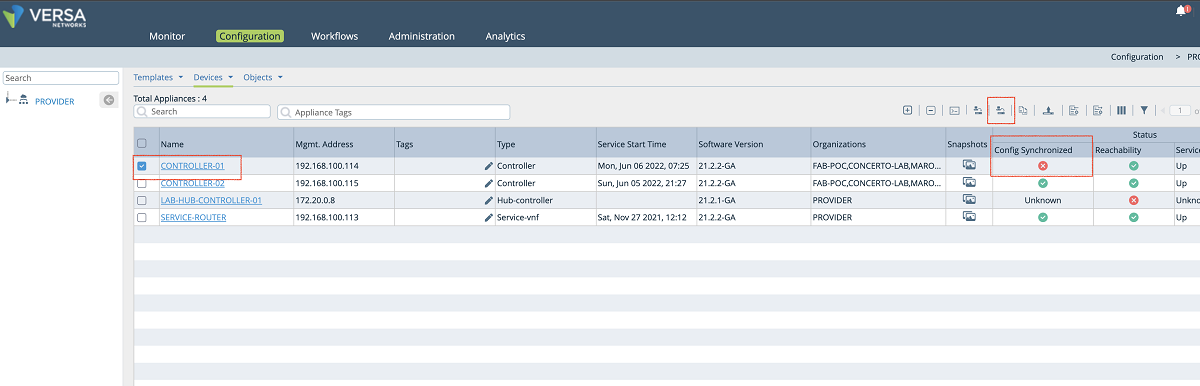
Figure 25: Synchronize Controller config with Director
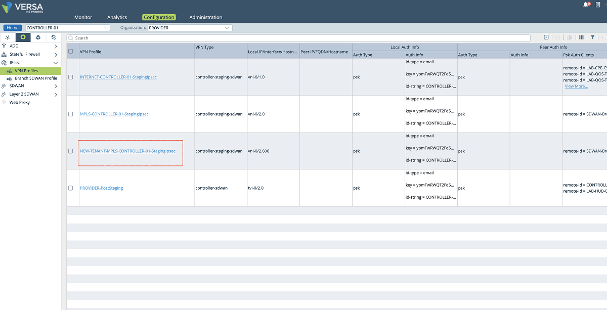
Figure 26: Controller IPsec VPN profiles
Appendix A: Controller Configuration
Interface and Network configuration:
set interfaces vni-0/2 unit 606 description NEW-TENANT-MPLS
set interfaces vni-0/2 unit 606 vlan-id 606
set interfaces vni-0/2 unit 606 enable true
set interfaces vni-0/2 unit 606 family
set interfaces vni-0/2 unit 606 family inet
set interfaces vni-0/2 unit 606 family inet address 172.16.16.2/30
set interfaces vni-0/2 unit 606 family inet6
set interfaces vni-0/2 unit 606 family inet6 mode router
set networks NEW-TENANT-MPLS-NETWORK interfaces [ vni-0/2.606 ]
set orgs org PROVIDER traffic-identification using-networks [ INTERNET MPLS NEW-TENANT-MPLS-NETWORK control ]
Virtual Router configuration:
set orgs org PROVIDER available-routing-instances [ Analytics-VR INTERNET-Transport-VR MPLS-Transport-VR NEW-TENANT-MPLS-VR PROVIDER-Control-VR ]
set orgs org PROVIDER owned-routing-instances [ Analytics-VR INTERNET-Transport-VR MPLS-Transport-VR NEW-TENANT-MPLS-VR PROVIDER-Control-VR ]
set routing-instances NEW-TENANT-MPLS-VR instance-type virtual-router
set routing-instances NEW-TENANT-MPLS-VR networks [ NEW-TENANT-MPLS-NETWORK ]
set routing-instances NEW-TENANT-MPLS-VR routing-options static route 0.0.0.0/0 172.16.16.1 none preference 1
SD-WAN configuration:
set orgs org NEW-TENANT sd-wan site wan-interfaces vni-0/2.606 sla-monitoring-policy SLAM_Policy_vni-0/2.606
set orgs org NEW-TENANT sd-wan site path-policy SLAM_Policy_vni-0/2.606 term To_All action specific-config fc_nc
set system sd-wan site wan-interfaces vni-0/2.606 transport-domains [ MPLS ]
set system sd-wan site wan-interfaces vni-0/2.606 inet
set system sd-wan site wan-interfaces vni-0/2.606 inet circuit-name NEW-TENANT-MPLS
set orgs org NEW-TENANT sd-wan site wan-interfaces vni-0/2.606 sla-monitoring-policy SLAM_Policy_vni-0/2.606
set orgs org NEW-TENANT sd-wan site wan-interfaces vni-0/2.606 management-traffic priority 0
IPSEC configuration:
set orgs org-services PROVIDER ipsec vpn-profile NEW-TENANT-MPLS-CONTROLLER-01-StagingIpsec vpn-type controller-staging-SD-WAN
set orgs org-services PROVIDER ipsec vpn-profile NEW-TENANT-MPLS-CONTROLLER-01-StagingIpsec alarms ipsec-state-change enable
set orgs org-services PROVIDER ipsec vpn-profile NEW-TENANT-MPLS-CONTROLLER-01-StagingIpsec alarms ike-state-change enable
set orgs org-services PROVIDER ipsec vpn-profile NEW-TENANT-MPLS-CONTROLLER-01-StagingIpsec alarms ike-auth-failure enable
set orgs org-services PROVIDER ipsec vpn-profile NEW-TENANT-MPLS-CONTROLLER-01-StagingIpsec local-auth-info
set orgs org-services PROVIDER ipsec vpn-profile NEW-TENANT-MPLS-CONTROLLER-01-StagingIpsec local-auth-info auth-type psk
set orgs org-services PROVIDER ipsec vpn-profile NEW-TENANT-MPLS-CONTROLLER-01-StagingIpsec local-auth-info id-type email
set orgs org-services PROVIDER ipsec vpn-profile NEW-TENANT-MPLS-CONTROLLER-01-StagingIpsec local-auth-info key xxxx
set orgs org-services PROVIDER ipsec vpn-profile NEW-TENANT-MPLS-CONTROLLER-01-StagingIpsec local-auth-info id-string CONTROLLER-01-staging@PROVIDER.com
set orgs org-services PROVIDER ipsec vpn-profile NEW-TENANT-MPLS-CONTROLLER-01-StagingIpsec local
set orgs org-services PROVIDER ipsec vpn-profile NEW-TENANT-MPLS-CONTROLLER-01-StagingIpsec local interface-name vni-0/2.606
set orgs org-services PROVIDER ipsec vpn-profile NEW-TENANT-MPLS-CONTROLLER-01-StagingIpsec routing-instance NEW-TENANT-MPLS-VR
set orgs org-services PROVIDER ipsec vpn-profile NEW-TENANT-MPLS-CONTROLLER-01-StagingIpsec tunnel-routing-instance PROVIDER-Control-VR
set orgs org-services PROVIDER ipsec vpn-profile NEW-TENANT-MPLS-CONTROLLER-01-StagingIpsec ipsec fragmentation pre-fragmentation
set orgs org-services PROVIDER ipsec vpn-profile NEW-TENANT-MPLS-CONTROLLER-01-StagingIpsec ipsec force-nat-t disable
set orgs org-services PROVIDER ipsec vpn-profile NEW-TENANT-MPLS-CONTROLLER-01-StagingIpsec ipsec mode tunnel
set orgs org-services PROVIDER ipsec vpn-profile NEW-TENANT-MPLS-CONTROLLER-01-StagingIpsec ipsec anti-replay enable
set orgs org-services PROVIDER ipsec vpn-profile NEW-TENANT-MPLS-CONTROLLER-01-StagingIpsec ipsec life duration 28000
set orgs org-services PROVIDER ipsec vpn-profile NEW-TENANT-MPLS-CONTROLLER-01-StagingIpsec ipsec hello-interval send-interval 10
set orgs org-services PROVIDER ipsec vpn-profile NEW-TENANT-MPLS-CONTROLLER-01-StagingIpsec ike group mod19
set orgs org-services PROVIDER ipsec vpn-profile NEW-TENANT-MPLS-CONTROLLER-01-StagingIpsec ike lifetime 28800
set orgs org-services PROVIDER ipsec vpn-profile NEW-TENANT-MPLS-CONTROLLER-01-StagingIpsec ike dpd-timeout 10
set orgs org-services PROVIDER ipsec vpn-profile NEW-TENANT-MPLS-CONTROLLER-01-StagingIpsec ike auth-domain MPLS-CONTROLLER-01-StagingIpsec-Domain
set orgs org-services PROVIDER ipsec vpn-profile NEW-TENANT-MPLS-CONTROLLER-01-StagingIpsec address-pools
set orgs org-services PROVIDER ipsec vpn-profile NEW-TENANT-MPLS-CONTROLLER-01-StagingIpsec address-pools address-range 172.20.2.0-172.20.2.63
set orgs org-services PROVIDER ipsec vpn-profile NEW-TENANT-MPLS-CONTROLLER-01-StagingIpsec address-pools netmask 255.255.255.192
set orgs org-services PROVIDER ipsec vpn-profile NEW-TENANT-MPLS-CONTROLLER-01-StagingIpsec address-pools accessible-subnets 172.20.2.0/26
set orgs org-services PROVIDER ipsec vpn-profile NEW-TENANT-MPLS-CONTROLLER-01-StagingIpsec address-pools accessible-subnets <Primary Director Southbound IP>/32
set orgs org-services PROVIDER ipsec vpn-profile NEW-TENANT-MPLS-CONTROLLER-01-StagingIpsec address-pools accessible-subnets <Secondary Director Southbound IP>/32
set routing-instances PROVIDER-Control-VR protocols bgp 1 prefix-list StagingPrefixes seq 3 address-family ipv4 unicast address-mask 172.20.2.0/26
set orgs org-services PROVIDER ipsec vpn-profile NEW-TENANT-MPLS-CONTROLLER-01-StagingIpsec remote-auth-type psk
set orgs org-services PROVIDER ipsec vpn-profile NEW-TENANT-MPLS-CONTROLLER-01-StagingIpsec psk-auth-clients
set orgs org-services PROVIDER ipsec vpn-profile NEW-TENANT-MPLS-CONTROLLER-01-StagingIpsec psk-auth-clients remote-client SD-WAN-Branch@PROVIDER.com id-type email
set orgs org-services PROVIDER ipsec vpn-profile NEW-TENANT-MPLS-CONTROLLER-01-StagingIpsec psk-auth-clients remote-client SD-WAN-Branch@PROVIDER.com key xxxx


